
DIY: Auxiliary on Base Fit


#102
 11-19-2007, 03:28 PM

thanks for the reply, i went ahead and did it last Friday. i did the mod with the Honda's 5 pin Aux jack and followed the previous postings on how to wire it up, for those who are wondering about the B4 connector, it seems to be working fine without the B3 and B4 shorted together as per the instructions with the radio shack 4 pin plug, so just wire it up accordingly to B3, B5, B13, B14, and B15 and you will be on your way
#103
11-22-2007, 12:05 AM
Can someone confirm that this is the pitch is being used in both the Sport Aux port and the back of the head unit?
As for spacing of the pins, I did not measure, but would bet that they were 0.100'' apart.
#104
11-22-2007, 03:14 AM
it's funny that you mention the cd-rom cables, the 4 pin one, because that is exactly what i used to make my connectors, two ends the back of the radio and one end +1 plug the aux jack. works just fine for me.
Last edited by TunaDaMan; 11-22-2007 at 03:15 AM. Reason: added a little more info

#106
12-12-2007, 08:49 PM
Finished!
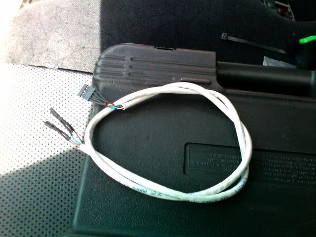
I ordered connectors from Minnesota, got the AUX piece from College Hills Honda, got some Cat-5 cabling and matching shrink tubing. Add in a crimper, a soldering iron, and an evening to tinker, and presto! One fully functional cable.
I installed it today with the help of a Honda service person. (I wasn't confident about pulling apart the dash and center console.) It was a huge struggle getting the head unit out, but everything works great. He hadn't pulled apart a Fit before, either. But we got it done and tested in less than an hour. Sounds great, and I'm using a dock connector cable (eBay) -- so the sound is better and the level is higher than with the headphone jack.
Thanks to everyone for all their great information and assistance!
BTW, I have spare parts to make another couple of cables. PM me if you're not thrilled about or interested in building your own, and would prefer to just buy one pre-made.
#107
12-15-2007, 04:12 AM
I couldn't get this to work. I got the 3.5mm plug all soldered with wires. Had the connection to the headunit as shown. Everything with the wires seemed right. The "AUX" button on the headunit still did nothing. Any ideas what the problem could be. Just got my Fit 3 days ago.
#108
01-14-2008, 10:55 PM
Shield GRD problem?
OK. My first cable was a little sloppy (the soldering and the crimp were a little fat and thus crammed into the plastic housing a little awkwardly). But after installing it, all seemed well and it played perfectly, so I left it in there rather than switching to my more polished second attempt.
However...
I would say roughly every couple of hours or so, I'll run through a stretch where the head unit loses the AUX signal very briefly. We're talking about a half-second, tops. When it does this, the screen switches from AUX to FM and then right back, and the sound just drops (it never actually plays the FM signal).
Even weirder, it happens fairly frequently with a handful of songs, but almost NEVER with most songs. Here's what I've ruled out:
1. I switched dock connector cables and used the iPod's headphone instead (still had the problem)
2. I switched iPods (still had the problem)
I know that the B4 is listed as the Auxiliary Jack Assembly (AUX SHIELD GND).
So my new working hypothesis goes something like this:
- My messy crimp and solder job on pins B3 or B5 (I forget which) has caused there to be some feint ability for the wiring to those pins to cross talk a little to B4.
- The output of some songs corresponds to frequencies which are just barely able to interfere.
- The head unit gets confused for a second about the ground signal, then continues to receive a signal from the AUX input, and switches back to AUX.
I don't really have any way to test this theory. Even replacing the cable (arduous) won't prove anything other than the cable is or isn't involved -- it won't pinpoint the issue.
Help! Anyone?
#109
01-22-2008, 03:02 PM

Instead of using any type of jacks, has anyone experimented with directly soldering one end of the 3.5mm cable (cutting the jack off) to the wires coming from the headunit? Obviously, it would be only 3 cables instead of 4 which would leave the b3 & b4 (i think) unconnected. would this work?
#110
03-01-2008, 04:13 PM

It may be easier if
We could get the 'Connector B' part and wire it to the Civic jack/cable posted earlier (Honda Civic Accessories - Audio and Electronic Accessories- 2006 - 2007). Any one know the part number or a source for the 20 pin connector B?
Last edited by Rob22315; 03-01-2008 at 04:16 PM.
#111
03-02-2008, 09:59 AM

5 pin connector
Guys radioshack didn't have a 4 pin connector (3.5mm) so i got a 5 pin.. can someone tell me if the configuration is the same? This is what i'm using but i tried it and it didn't work..
I've got wires solder to pins 1 - 4 and then i have it connected like smeisters original post. Do i need something connected to pin 5? Please help..

I've got wires solder to pins 1 - 4 and then i have it connected like smeisters original post. Do i need something connected to pin 5? Please help..
#112
03-04-2008, 11:55 AM
Connector # needed
To anyone who has or is taking apart their stock radio - can you find any identification marks on the mysterious 20-pin (or 'B') connector on the back of the radio? College Hills Honda claims the Fit uses Mitsumi connectors but I didn't see anything like it on the Mitsumi website.
I'd like to be able to pre-wire the connector, then install it without fully removing the radio - assuming I can squeeze a connector up around the vent/AC controls.
I'd like to be able to pre-wire the connector, then install it without fully removing the radio - assuming I can squeeze a connector up around the vent/AC controls.
#113
03-04-2008, 11:43 PM
Guys radioshack didn't have a 4 pin connector (3.5mm) so i got a 5 pin.. can someone tell me if the configuration is the same? This is what i'm using but i tried it and it didn't work..
I've got wires solder to pins 1 - 4 and then i have it connected like smeisters original post. Do i need something connected to pin 5? Please help..
I've got wires solder to pins 1 - 4 and then i have it connected like smeisters original post. Do i need something connected to pin 5? Please help..
#114
03-05-2008, 06:28 PM

so i decided to give this DIY a go.
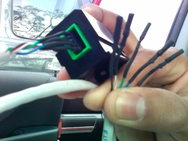
so after about a half an hour of drawing out how was going to wire the aux jack in. i came out with this. i felt accomplished because it looked like it FiT in perfectly with all the other wires. what i used was a cat 5 cable. cut the ends off. and crimped and soldered female db9 pins on one end. and found a 5 pin housing for the end that goes into the aux jack. the housing used its own female pins but i crimped and soldered those and popped them in the hole according to the wireing diagram on the first page. the 5 pin housing goes into the aux perfectly and stays snug. the most difficult part was putting the db9 pins into the back of the deck. i didnt have anymore of the pins for the housings or else i would have done the side that goes into the stereo head unit with the same housing.would have been alot easier but the end result for me was pleasing. then to give it that clean look i used shrink tube to cover the wires instead of electrical tape, and everything looks as clean as possible. im willing to make some of these if anyone likes it. or you can do it yourself using parts you can find at a local Frys electronics. and everything looks as if it suppose to be there. thank you for such a great write up. and
#115
03-06-2008, 04:51 PM
Does anyone know if there is a difference between the B3, B4 & B5 connectors? Since they are all AUX GND connectors. The reason I ask is that my current setup is how smeister explained with 4 wires (B3 & B4 connected together). Now I want to use the Honda part that uses 5 wires (db_et_ac method) which suggests that B3 & B5 be seperate and should run to the aux connector. So I was wondering if I can use my current wiring and not pull out the main headunit. I would plan to use the current wire connected to B3 & B4 to run to the inputs Cavity 3 & Cavity 2 (of the honda aux connector).
3/14 Update: It did work. Pin 2 & 3 both connected to B3&B4. Works perfectly.
3/14 Update: It did work. Pin 2 & 3 both connected to B3&B4. Works perfectly.
Last edited by pratik5705; 03-14-2008 at 12:55 PM.
#116
03-15-2008, 01:06 AM

my notes
I was able to do this mod on my new 08 base fit. It was more work than I figured but I am happy with the result. A couple of things I'd like to share...
- I used the ID bit cables from cyberguys recommended in the thread. They are 2 feet long and I didn't bother splicing them to shielded ethernet cable, because they are short enough to make the run without shielding. The examples pictured here look very pro, but a 2 foot run of cable with line level audio can survive OK without the shielding if you don't want to bother; at least any noise picked up is not going to be louder than the real world ambient noise level. Another option is to use shielded audio cable that has 4 conductors in a shield. Canare star quad cable would work well in this case.
- Because of the pins on the back of the radio don't all line up in pairs, I ended up cutting the double pin connectors in two for two of the cables. That's a hack that isn't totally lovely but doesn't cause a problem if you only remove the plastic from the connectors that needs to be removed. Otherwise, 3 single runs plus a pair would be best.
- I found I didn't need to remove the electrical connections to the head unit to do this. Because of this, I didn't disconnect the battery. I didn't want to lose the engine's computer data, but honestly I don't know how this works.
- I took a very small bite out of the top right hand side of the dashboard just about the head unit after loosening it. There is a sort of a tendency for that corner to snap back onto the dashboard, causing that sort of damage. If I did this again, I would try to cover that corner up with something to protect it before pulling out the head unit.
- Removing the head unit was far more difficult than I imagined. By some combination of giving up and trying again for the better part of an afternoon, I was able to massage it loose. When I finally did get most of the clips to pop off after ferocious tugging, a couple of the metal clips that were holding the head unit it popped of and went awol. I wish I could have kept all those in place. I had to pull that thing much longer and harder than felt comfortable to me, but it did come off in one piece.
So although it didn't go together exactly like it came apart because of the missing clips, I do have a working result.
Last edited by Mad Fitter; 03-15-2008 at 01:10 AM.
#117
03-22-2008, 03:11 AM
hey there,
I am basically in the same dilemma just in a slightly different way. I have an after market deck (not installed yet) but on the rear of my deck it actually has a 3.5mm AUX in.
What I would like to do is somehow wire the existing original AUX jack to a 3.5mm headphone tip to plug directly into the back of my deck.
Any suggestions? Has anyone done this to theirs?
-Greg
#120
03-26-2008, 05:45 PM
I just did this DIY, using the OEM aux port, some ID Bit cables from the local computer repair store (had to dice them up, since they came in 4-pin arrays), and the iTunes head unit removal instructions. Great mod!! Now my base Fit has Zune capabilities! Props to those who have contributed, esp db et ac. Thanks much 