
DIY: Auxiliary on Base Fit
#181
 08-21-2014, 01:27 AM


Confirmed. This $8 aux was plug and play.
This looks awfully close to the fit diagram? $8 plug and play
Can any confirm??
Aux Cable 3 5mm Input Audio Cable for Honda CRV Honda Accord Civic | eBay

matches the stock radio plug #3?

Item description mentions compatible with 06 civic.
Here's the 06 civic radio

Can any confirm??
Aux Cable 3 5mm Input Audio Cable for Honda CRV Honda Accord Civic | eBay
matches the stock radio plug #3?
Item description mentions compatible with 06 civic.
Here's the 06 civic radio
#182
09-20-2014, 09:50 PM

There seem to be many issues with missing pictures, and a general lack of a summary of the instructions on how to add the aux jack. I will do my best to summarize how to do it. I don't have any pictures of my own, but I do have a few of the pinout diagrams from previous posts.
In this thread there are 3 basic approaches to installing the aux jack:
Method 1
Install a generic panel mount 1/8" audio jack in the cover for the opening in the center console where the OEM jack is installed on sport models. This method also requires improvising pins to connect to connector B on the back of the radio. Most people have used PC motherboard heat-sink fan connectors or cordless phone battery connectors to connect to the back of the radio. This was the original method outlined by the OP. This seems to be the cheapest, but most work intensive method. I will not go into a lot of detail about this method because there are many different parts and exact ways to do it since you are providing your own generic parts.
Method 2
Order the OEM parts 39117-SWA-A00 (CR-V wiring part that has both internal OEM connectors) and 39112-SAA-J02ZA (the actual OEM jack) from College Hills / Bernardi / Honda Parts Now / etc. and splice in a 3-4' length of 5-conductor cable into 39117-SWA-A00 to make it long enough for the Fit. You will want to solder and use heat-shrink tubing for the splicing. Once you have extended 39117-SWA-A00, you simply plug one end into connector B on the radio and the other end into the back connector of the OEM aux jack. This method is probably the most expensive, but gives you the most OEM like result. This is the approach that I used.
Method 3
Install the plug-and-play cable from here. It plugs into connector B on the back of the radio. This is probably the easiest way to do it, but you end up with a cable coming out of your dash somewhere rather than a plugin jack on the center console.
Pulling the head unit
For all of these methods, you will at least have to pull the head unit to get to connector B on the back of the radio. The instructions here (up to step 13) should tell you everything you need to know to pull the head unit. The previous post here also has some good pictures that are still up.
Selecting cable
Methods 1 and 2 require that you provide your own cable to connect the jack to the connector for the back of the radio. Most people use Cat 5/5e/6 Ethernet cable for this. I have found that due to the very small gauge of the conductors in Ethernet cable and the fact that the individual conductors are not meant to be stripped, it is hard to work with. If you can find some other larger gauge 5-conductor stranded cable, I would go for that instead. However, 5-conductor thermostat cable is usually solid conductor, and should not be used in automotive applications.
Removing the center console
Methods 1 and 2 also require that you remove the center console to install the jack into the OEM location near the 12v power jack. A previous post by nttdemented has a good description of how to do this:
The clips on the front of the console look like a small circle in a bigger circle. To remove, you push in small circle in, then the bigger circle should be free to pull out. Also on the AT shifter, there is nothing to unscrew. The shifter stays, and the console comes out from around it. The cover that is over the OEM jack location is held in by screws from underneath. Remove the screws and the cover. If using method 1, drill a hole in the cover for your panel mount jack, and install it into the cover. Then put the cover back. If using method 2, put the OEM jack where the cover was and put the screws back in place.
Pinout references
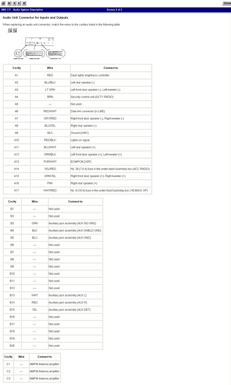
Connector B on the radio is the one that is used for the aux input. It is not used for anything else and has nothing connected to it on a base Fit:
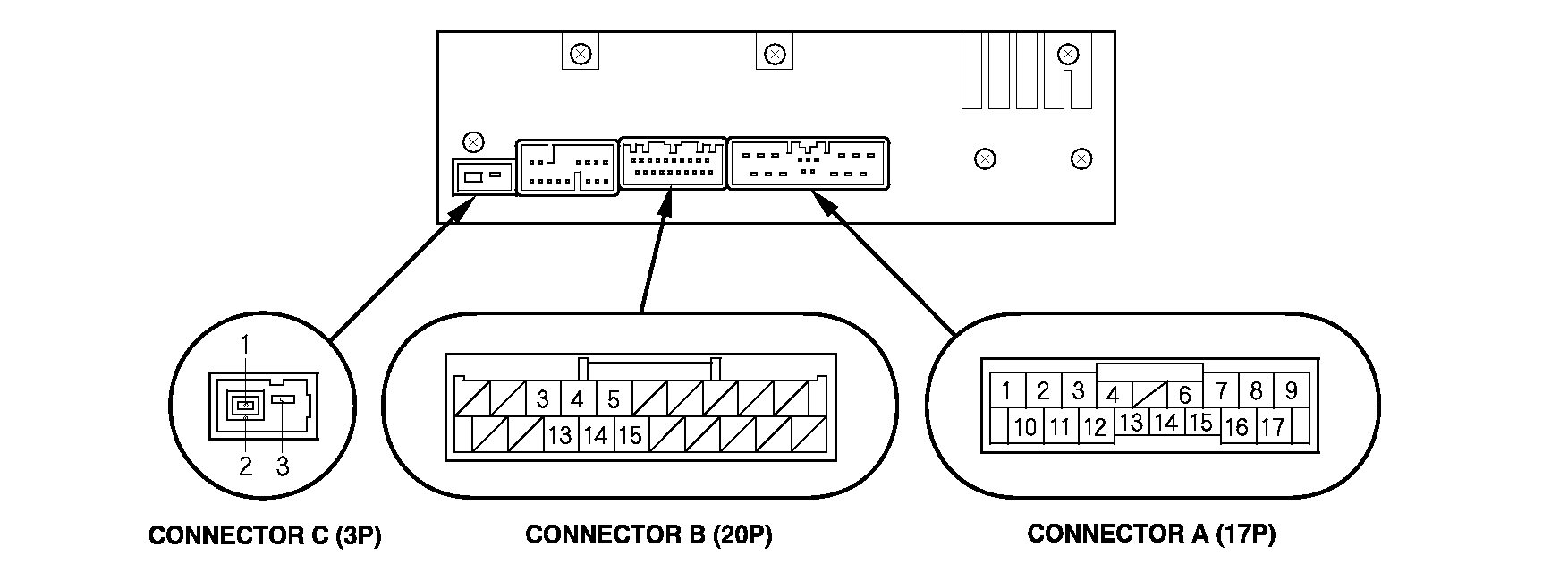
Pinout details for the radio connectors. Please note that all methods documented here leave B4 unconnected.
Pinout details for the back connector of the OEM jack:
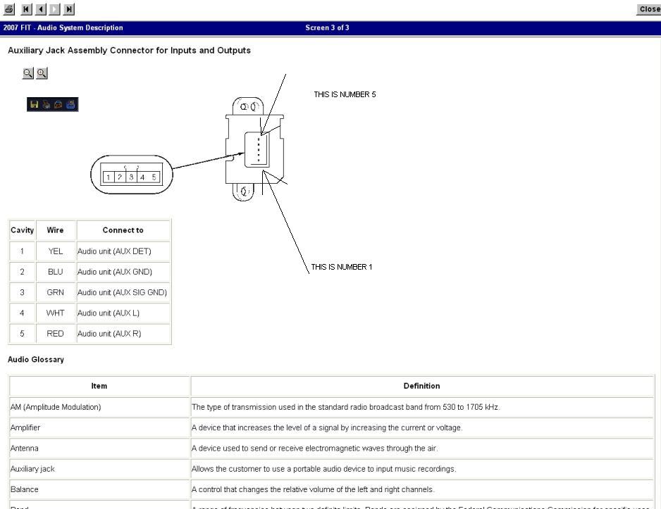
Notes on the aux detection circuit
You will note that there are 5 pins on the OEM aux jack that all connect to the radio which is more than the 3 one would expect to see. This is because there is another circuit in addition to the audio signal that is intended to tell the radio when something is plugged into the jack. When the radio detects that something is plugged in, the aux option on the radio can be selected. This is actually the reason that the aux button does nothing before the mod. The circuit will never be closed when nothing is plugged into connector B of the radio. The aux button also does nothing when nothing is plugged into the aux jack after the mod, which I presume is the same behavior as the sport. Another implication of this is that if you are using method 1 to add the aux jack, you must jumper B5 to B15 on the radio for the aux option to be available since your generic 1/8" jack will likely only have the 3 signal connections. Some generic 1/8" jacks have a switch similar to the OEM jack. In that case you can connect B5 and B15 to that switch and get the same functionality. I presume that the plug-and-play cable used in method 3 has B5 connected to B15, but I have never seen it.
I know this is not a complete step-by-step, but hopefully it helps!
In this thread there are 3 basic approaches to installing the aux jack:
Method 1
Install a generic panel mount 1/8" audio jack in the cover for the opening in the center console where the OEM jack is installed on sport models. This method also requires improvising pins to connect to connector B on the back of the radio. Most people have used PC motherboard heat-sink fan connectors or cordless phone battery connectors to connect to the back of the radio. This was the original method outlined by the OP. This seems to be the cheapest, but most work intensive method. I will not go into a lot of detail about this method because there are many different parts and exact ways to do it since you are providing your own generic parts.
Method 2
Order the OEM parts 39117-SWA-A00 (CR-V wiring part that has both internal OEM connectors) and 39112-SAA-J02ZA (the actual OEM jack) from College Hills / Bernardi / Honda Parts Now / etc. and splice in a 3-4' length of 5-conductor cable into 39117-SWA-A00 to make it long enough for the Fit. You will want to solder and use heat-shrink tubing for the splicing. Once you have extended 39117-SWA-A00, you simply plug one end into connector B on the radio and the other end into the back connector of the OEM aux jack. This method is probably the most expensive, but gives you the most OEM like result. This is the approach that I used.
Method 3
Install the plug-and-play cable from here. It plugs into connector B on the back of the radio. This is probably the easiest way to do it, but you end up with a cable coming out of your dash somewhere rather than a plugin jack on the center console.
Pulling the head unit
For all of these methods, you will at least have to pull the head unit to get to connector B on the back of the radio. The instructions here (up to step 13) should tell you everything you need to know to pull the head unit. The previous post here also has some good pictures that are still up.
Selecting cable
Methods 1 and 2 require that you provide your own cable to connect the jack to the connector for the back of the radio. Most people use Cat 5/5e/6 Ethernet cable for this. I have found that due to the very small gauge of the conductors in Ethernet cable and the fact that the individual conductors are not meant to be stripped, it is hard to work with. If you can find some other larger gauge 5-conductor stranded cable, I would go for that instead. However, 5-conductor thermostat cable is usually solid conductor, and should not be used in automotive applications.
Removing the center console
Methods 1 and 2 also require that you remove the center console to install the jack into the OEM location near the 12v power jack. A previous post by nttdemented has a good description of how to do this:
To get to the AUX jack's position you have to remove the entire center console by first unscrewing the shift knob off the shifter, poping out the plastic tab under the emergency brake (this will allow for clearance with the e-brake when pulling out the center console) and after that just remove the two clips (one on each side) that are at the front of the center consle and two screws at the back (one on each side also) these can be easily accessed by rolling both front seats forward.
Pinout references
Connector B on the radio is the one that is used for the aux input. It is not used for anything else and has nothing connected to it on a base Fit:
Pinout details for the radio connectors. Please note that all methods documented here leave B4 unconnected.
Pinout details for the back connector of the OEM jack:
Notes on the aux detection circuit
You will note that there are 5 pins on the OEM aux jack that all connect to the radio which is more than the 3 one would expect to see. This is because there is another circuit in addition to the audio signal that is intended to tell the radio when something is plugged into the jack. When the radio detects that something is plugged in, the aux option on the radio can be selected. This is actually the reason that the aux button does nothing before the mod. The circuit will never be closed when nothing is plugged into connector B of the radio. The aux button also does nothing when nothing is plugged into the aux jack after the mod, which I presume is the same behavior as the sport. Another implication of this is that if you are using method 1 to add the aux jack, you must jumper B5 to B15 on the radio for the aux option to be available since your generic 1/8" jack will likely only have the 3 signal connections. Some generic 1/8" jacks have a switch similar to the OEM jack. In that case you can connect B5 and B15 to that switch and get the same functionality. I presume that the plug-and-play cable used in method 3 has B5 connected to B15, but I have never seen it.
I know this is not a complete step-by-step, but hopefully it helps!
#183
11-27-2014, 08:10 PM

Wondering if anyone tried this option:
http://www.ebay.com/itm/Car-Interface-Adapter-AUX-In-Input-For-Civic-/121423669191?pt=Motors_Car_Truck_Parts_Accessories&fits=Make%3AHonda&hash=item1c456a27c7&vxp=mtr
Looking at pictures - it looks like the correct pins are wired on the B connector (3, 4, 5, 3, 14, 15)...and there is a female 1/8" jack already installed at the other end of the cable...you just need to make a proper size hole and mount the jack...
Last edited by gstankovic; 11-27-2014 at 08:15 PM.
#184
11-29-2014, 04:50 PM
read two post above, I've confirmed it working.
Wondering if anyone tried this option:
Ebay Link
Looking at pictures - it looks like the correct pins are wired on the B connector (3, 4, 5, 3, 14, 15)...and there is a female 1/8" jack already installed at the other end of the cable...you just need to make a proper size hole and mount the jack...
Ebay Link
Looking at pictures - it looks like the correct pins are wired on the B connector (3, 4, 5, 3, 14, 15)...and there is a female 1/8" jack already installed at the other end of the cable...you just need to make a proper size hole and mount the jack...
#185
11-29-2014, 06:31 PM
mxl180, your post refers to OEM connector to 1/8" PLUG adapter ..the part I am referring to is OEM connector to 1/8" JACK adapter - which can be installed in a similar way to OEM AUX jack...so you would have a clean install instead of a cable with a 1/8" jack dangling around...
#186
03-01-2015, 04:24 PM

Wondering if anyone tried this option:
Ebay Link
Looking at pictures - it looks like the correct pins are wired on the B connector (3, 4, 5, 3, 14, 15)...and there is a female 1/8" jack already installed at the other end of the cable...you just need to make a proper size hole and mount the jack...
Ebay Link
Looking at pictures - it looks like the correct pins are wired on the B connector (3, 4, 5, 3, 14, 15)...and there is a female 1/8" jack already installed at the other end of the cable...you just need to make a proper size hole and mount the jack...
#187
03-01-2015, 07:40 PM
Yup, I installed it - works great, plug and play.
Drill a hole in the middle of the plastic piece covering a hole where OEM jack
would go, and that's it...you'll still need to pull the radio out yo plug the connector, and route the cable...
Drill a hole in the middle of the plastic piece covering a hole where OEM jack
would go, and that's it...you'll still need to pull the radio out yo plug the connector, and route the cable...
#189
03-29-2015, 10:53 PM

Finally
Thank you so much to everyone who posted about the female aux-in connector. Several months ago I began this journey starting with an aux/usb adapter from China I got on eBay, a faulty USAspec iPod/aux adapter, a GTA car kit (iPod/aux), and then, finally, the $7 female jack i got on eBay. (link in this thread shows the same thing, the Civic female-aux-in for $10).
Because this thread obviously has very old origins, I had always overlooked it, intimidated by the little bit of soldering etc that would be required. I wish I had used my head and looked at the more recent thread pages. This female jack is plug and play and was the easiest solution out there, and I've tried them all. No ground loop while charging (finally!), least static, no clipping from iPod inputs from GTA/USAspec (signal too hot for radio, I found...clips a lot).
Also, I must say, the mounting of the female aux-in was so easy. Removing the console is super easy. Routed the cable through, drilled a hole with a 1/4" bit, fed it through, used the screwable securing/mounting ring, and voila. Closest thing to the OEM...and again $7!!!
#190
04-11-2015, 11:45 AM

Hey guys!
Sorry in advance for my bad english, I'm italian
Anyway, just two quick questions:
1 - I have a 2004 jazz and I would like to know if this cheap "miracle cable" can do the trick for my car
http://www.ebay.com/itm/Car-Interface-Adapter-AUX-In-Input-For-Civic-/121423669191?pt=Motors_Car_Truck_Parts_Accessories&fits=Make%3AHonda&hash=item1c456a27c7&vxp=mtr
My radio unit looks like the one that can be seen in this guide -> CLICK <- ..the cable is going to fit in the green piece? or in the white one? ...or not at all?
This cable CAN'T keep the iPod charged, right? I need to find another solution for the charge problem.. i think!
2 - IF It's going to work, where is supposed to end the aux-in? did it have to come out from the little piece of unused plastic near the cigarette lighter (this one, for better understanding -> CLICK)? I don't know how to do it, honestly! There is a DIY guide for this too?
Thanks!
Last edited by .Shane.; 04-11-2015 at 12:40 PM.
#191
04-13-2015, 10:49 PM
hi .Shane.,
Unfortunately no, this cable will not work for you as your radio does not have the right connector.
Unfortunately no, this cable will not work for you as your radio does not have the right connector.

#193
04-14-2015, 04:14 PM
The GTA car kit or USAspec kit would work for you, it looks like. Appears you have the right connector for those.
Also, if you have a friend that's handy with electronics, you could get them to wire that "miracle" plug/female jack to the right pins on the back of your radio. I imagine you might be able to do it without any soldering, maybe just some electrical tape/heat shrink. The physical connection would be the only "difficult" part, just have to figure out how to keep it connected permenantly to the back of that port.
Also, if you have a friend that's handy with electronics, you could get them to wire that "miracle" plug/female jack to the right pins on the back of your radio. I imagine you might be able to do it without any soldering, maybe just some electrical tape/heat shrink. The physical connection would be the only "difficult" part, just have to figure out how to keep it connected permenantly to the back of that port.

Thread
Thread Starter
Forum
Replies
Last Post