
DIY Turn Signal Mirrors (winkers)
#141
 12-22-2009, 12:43 AM


Im anxious to see how your installation progresses. Please take as many pics as you can.
#142
01-07-2010, 05:34 PM

I just installed my winkers last night and was wondering if anyone knows which wires do I connect to, to make my winkers flash when I lock and unlock my car. They only flash when I turn on my turn signal, I was noticing that when I lock or unlock my car the turn signal lights flash but my winkers don't. Please help!


#146
02-13-2010, 09:23 PM

I got my blinker kit from Panson. Slightly different, but functionally equivalent.
Painted the shells. Installed the left one with a bit of trouble - mostly I didn't follow the photo directions for fishing the wire through the rubber boot between door and body. It is important to pull the boot out completely, so the fish wire is straight. (Trying to run the fish wire through the curved boot is nearly impossible.)
I ran out of dry daylight, but replaced the passenger mirror shell without opening to door panel (yet).
Note for Panson's kit: Pull the lamp wires through the mirror and into the door cavity before installing the connector on the mirror end. The connector is meant to be located adjacent to the connector for the mirror position power. Nice touch.
When we get a break in the rain I'll wire them up. The color codes above match the wiring diagram from Honda, so I'm sure they will work fine.

#149
02-17-2010, 12:05 AM
window-wire interference
Alll you body experts will laugh, but I had to remove the door panels to re-route the winker wire out of the way of the windows.
Sure, the picture was clear, but I need to know why, and usually have to find out by reworking. Sigh.
At any rate, the windows work fine again, with no strange noises.
(I still have not had enough dry weather to actually connect the winkers to the turn signal circuits. Shouldn't take long, tho)
Sure, the picture was clear, but I need to know why, and usually have to find out by reworking. Sigh.
At any rate, the windows work fine again, with no strange noises.
(I still have not had enough dry weather to actually connect the winkers to the turn signal circuits. Shouldn't take long, tho
)

#151
02-21-2010, 03:13 PM
RC Installation
RC installation.
1. Remove instrucment panel. See demo here.
TK69A00J26220234701KDAV10
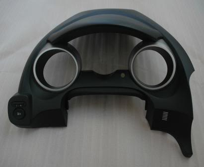
2. The instrument panel - front.
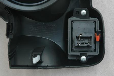
3. The back of the instrument panel.
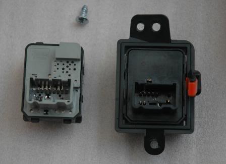
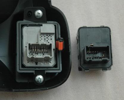
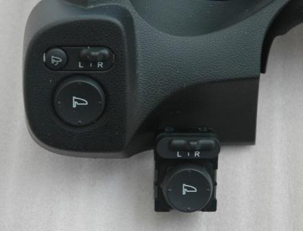
3. Unscrew 2 screws to remove RC bracket from the instrument panel. Left is RC with auto-fold function. Right is the USDM RC in its bracket.
4. Swap the RC with auto-fold function with USDM RC.
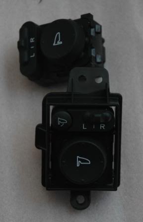
5. Put the bracket with new RC back to the instrument panel.
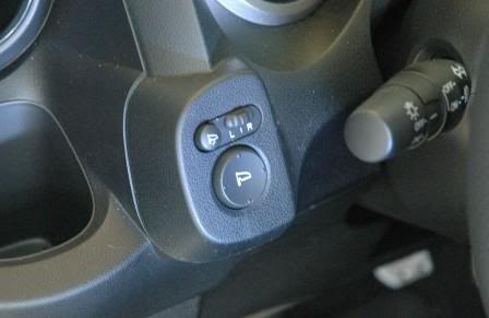
6. New RC with auto-fold function.
7. Install the instrument panel back to the car by reversing step 1.
8. Test functionality of the new RC with your USDM mirrors.
This RC with auto-fold function should be PnP installation (direct swap). However, there are 2 more wires that need to connect to it. I will show in the next step.
1. Remove instrucment panel. See demo here.
TK69A00J26220234701KDAV10
2. The instrument panel - front.
3. The back of the instrument panel.
3. Unscrew 2 screws to remove RC bracket from the instrument panel. Left is RC with auto-fold function. Right is the USDM RC in its bracket.
4. Swap the RC with auto-fold function with USDM RC.
5. Put the bracket with new RC back to the instrument panel.
6. New RC with auto-fold function.
7. Install the instrument panel back to the car by reversing step 1.
8. Test functionality of the new RC with your USDM mirrors.
This RC with auto-fold function should be PnP installation (direct swap). However, there are 2 more wires that need to connect to it. I will show in the next step.
Last edited by FITMugen; 02-21-2010 at 03:46 PM.
#152
02-21-2010, 04:27 PM
can't wait for everything to be wired up, +rep FITMugen. now all I need is to score myself a set of OEM folding mirror and switch.
#153
02-21-2010, 09:41 PM
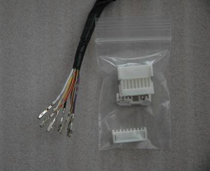
RC Switch plug
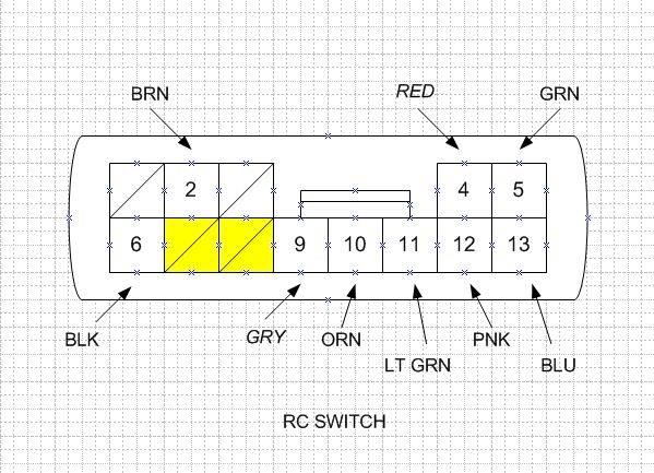
When you look at RC switch.
USDM RC switch, PIN 1, 3, 7 and 8 are not in use.
JDM RC switch with auto-fold will use PIN 7 and 8 (YELLOW). You will need 2 pigtails P/N: 04320-SAA-A00 and snap them into RC switch harness plug.

Run 4 cables, 2 for auto-fold, and another 2 for heated mirrors between fuse box area and left/right doors. Total is 8 cables, 4 for each side. Leave some extra wires at both end.
USDM RC switch, PIN 1, 3, 7 and 8 are not in use.
JDM RC switch with auto-fold will use PIN 7 and 8 (YELLOW). You will need 2 pigtails P/N: 04320-SAA-A00 and snap them into RC switch harness plug.
Run 4 cables, 2 for auto-fold, and another 2 for heated mirrors between fuse box area and left/right doors. Total is 8 cables, 4 for each side. Leave some extra wires at both end.
#154
02-22-2010, 08:22 PM
My mirrors, parts, and installation are shown in this post:
https://www.fitfreak.net/forums/gene...tml#post816836
https://www.fitfreak.net/forums/gene...tml#post816836
#155
02-28-2010, 11:13 AM
update
The way I installed my side mirrors was one feature at a time.
1. Installed RC switch to work existing USDM OEM mirrors. So I can test power mirror functions.
2. Installed JDM side mirrors with integrated turn signal and tested power mirror function.
3. Wired turn signal.
4. Wired auto-fold feature.
The steps of removing USDM side mirrors from and installing JDM side mirrors to the car are very much the same as Niko3257. This is what it is look like.
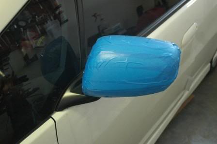
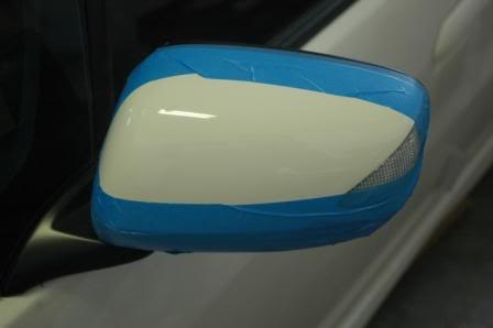
Picture 1.
I wrapped the mirrors with masking tape so they would not scratch. Then I removed the masking tape when they were done.
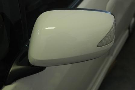
Picture 2. Removed masking tape.
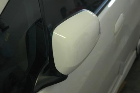
Picture 3. Left mirror in open position.
Picture 4. Left mirror in close position.
There are 3 wires for power mirror.
Left Mirror
HARNESS - MIRROR
GRN - YEL/WHT
ORN - YEL/ORN
PNK - YEL/BLK
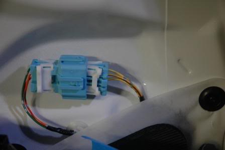
This is JDM left mirror plug.
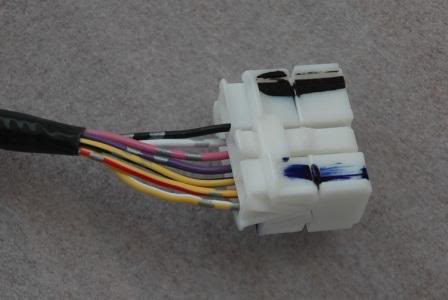
I remove wires/pins from the connector.
Do the same for USDM mirror connectors. Then you can reuse the OEM connector.
This is what it looks like when you are done. You cannot even tell that I already swap wires/pins.
There are 4 wires left for auto-fold and turn signal.
I will add additional steps later.
1. Installed RC switch to work existing USDM OEM mirrors. So I can test power mirror functions.
2. Installed JDM side mirrors with integrated turn signal and tested power mirror function.
3. Wired turn signal.
4. Wired auto-fold feature.
The steps of removing USDM side mirrors from and installing JDM side mirrors to the car are very much the same as Niko3257. This is what it is look like.
Picture 1.
I wrapped the mirrors with masking tape so they would not scratch. Then I removed the masking tape when they were done.
Picture 2. Removed masking tape.
Picture 3. Left mirror in open position.
Picture 4. Left mirror in close position.
There are 3 wires for power mirror.
Left Mirror
HARNESS - MIRROR
GRN - YEL/WHT
ORN - YEL/ORN
PNK - YEL/BLK
This is JDM left mirror plug.
I remove wires/pins from the connector.
Do the same for USDM mirror connectors. Then you can reuse the OEM connector.
This is what it looks like when you are done. You cannot even tell that I already swap wires/pins.
There are 4 wires left for auto-fold and turn signal.
I will add additional steps later.
Last edited by FITMugen; 02-28-2010 at 12:31 PM.
#157
03-21-2010, 09:48 PM
Auto-fold side mirrors
How to connect auto-fold feature?
Assume that your side mirrors have auto-fold feature - actuator.
These are part numbers for reference.
Right LED Folding mirror, P/N 76208-TFO-J11
Left LED Folding mirror, P/N 76258-TFO-J11
Power folding type mirror switch assy, P/N 35190-TFO-J01
Wire repair sub cord (10 wires per part# ), P/N 04320-SAA-A00
If you look at RC switch harness for USDM GE8 at PIN 7 and 8, they are empty. Slide 2 wires repair sub cord to PIN 7 and 8. Run 2 wires (YEL and GRY prefer) to side door. Connect YEL wires to PIN 8 and GRY wires to PIN 7 at the RC Switch end.
Connect YEL wire to side mirror PIN 3 and GRY wire to side mirror PIN 8.
Test your mirrors.
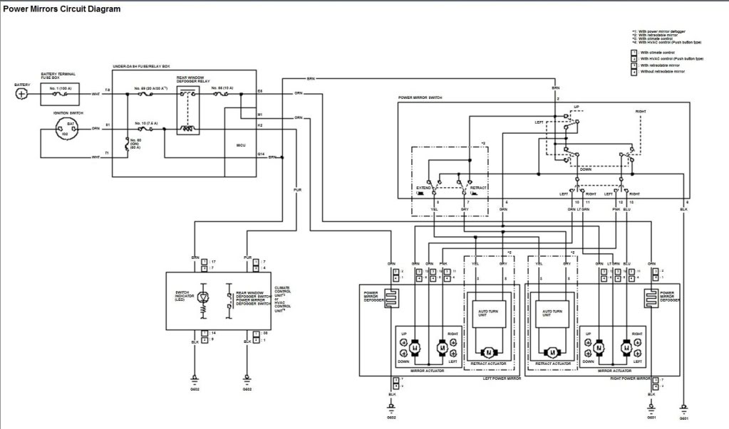
This diagram will help for troubleshooting.
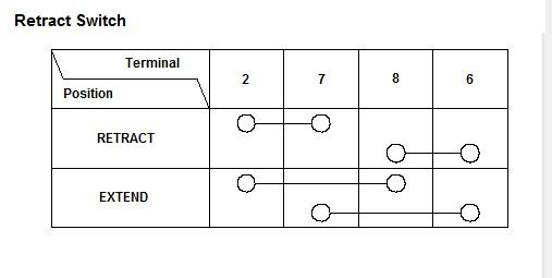
Please let me know if you need any clarifications.
Cheer.
Assume that your side mirrors have auto-fold feature - actuator.
These are part numbers for reference.
Right LED Folding mirror, P/N 76208-TFO-J11
Left LED Folding mirror, P/N 76258-TFO-J11
Power folding type mirror switch assy, P/N 35190-TFO-J01
Wire repair sub cord (10 wires per part# ), P/N 04320-SAA-A00
If you look at RC switch harness for USDM GE8 at PIN 7 and 8, they are empty. Slide 2 wires repair sub cord to PIN 7 and 8. Run 2 wires (YEL and GRY prefer) to side door. Connect YEL wires to PIN 8 and GRY wires to PIN 7 at the RC Switch end.
Connect YEL wire to side mirror PIN 3 and GRY wire to side mirror PIN 8.
Test your mirrors.
This diagram will help for troubleshooting.
Please let me know if you need any clarifications.
Cheer.
Last edited by FITMugen; 03-21-2010 at 09:50 PM.

#160
08-16-2010, 04:07 PM
I just received my winkers. Slightly different. They have three wires. Only one know what the third would be for? I suspect it is wired into headlights and so the lights are on all the time until you turn on signal. If so which wire do I need to connect to in the fuse box?
Now next question. How the heck do you get the arm rest off? Just pull real hard? Do you not have to depress the tabs somehow?
Thanks
Now next question. How the heck do you get the arm rest off? Just pull real hard? Do you not have to depress the tabs somehow?
Thanks
Last edited by Black3sr; 08-17-2010 at 06:29 AM.