
Arduino Auto Headlight Circuit
#1
 09-05-2014, 11:43 AM

Arduino Auto Headlight Circuit
This is a brief write up of what I did to add an Auto headlight feature to my 2013 Fit Sport Nav. Standard disclaimers apply: I am in no way responsible if you try to do this and screw up your car. There are many ways to do this, but as a coder, I decided to use a programmable bit at the heart of it. The circuit turns on the headlights whenever the ambient light level falls below a programmed level. I prefer my Nav screen to not always be dark (night mode) when the headlights are on, so I added a second output to control the Nav illumination. I grabbed much of the info needed for this mod off sites like this, so I decided to contribute back what I learned in the process. This write up is not extremely detailed, but I hope it provides enough info if you want to attempt it yourself. If something is not clear, ask and I will try and respond.
The Hardware
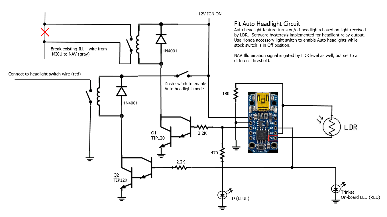
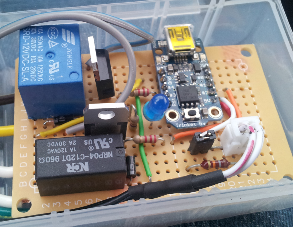
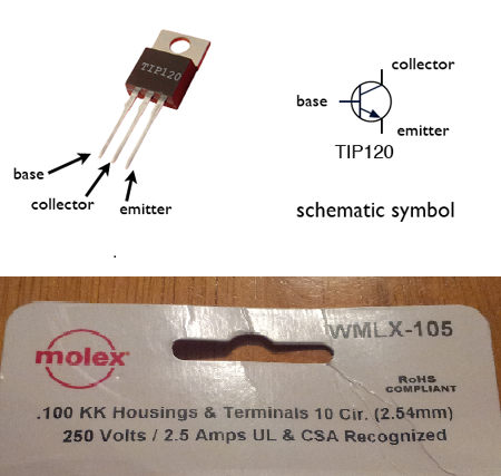
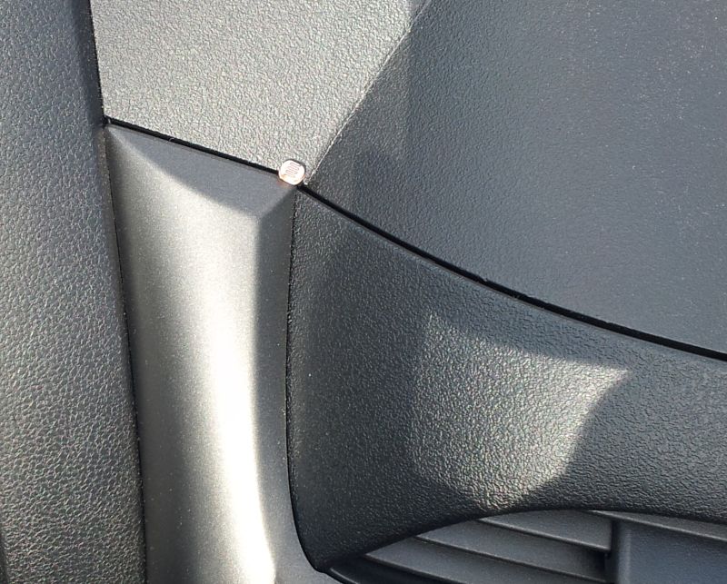
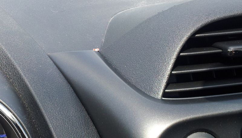
I based the design on a very small Arduino processer, the Adafruit Trinket (Adafruit Trinket - Mini Microcontroller - 5V Logic ID: 1501 - $6.95 : Adafruit Industries, Unique & fun DIY electronics and kits). It only costs about $7 and requires nothing more than a mini-B USB cable and some free software downloaded from Adafruit for your PC to program it. Once programmed, the trinket acts as a dedicated circuit (no need to keep a PC connected). My circuit design is based on some examples using a light dependent resistor (LDR) on the Adafruit website. I purchased most of the electronic parts from Adafruit, but you can also get them from Digikey/Mouser/etc. The circuit samples the value of the LDR and decides to put out a 1 (5V) or a 0 (0V) based on the current light level. The trinket�s low current outputs are used to drive transistors, which in turn can drive enough current to switch on a 12V relay. Separate outputs are used for the headlight function and Nav illumination function so they can be switched at different light levels. The LDR is part of a voltage divider on input 2 of the trinket. As the light level goes up, the resistance of the LDR goes down, causing the voltage level on pin 2 to go up. The LDR for this circuit is attached to a longer wire pair (about 3ft), so the LDR can be located on the dash while the rest of the circuit is installed near the fuse box. I did not drill any holes for this install. I simply placed the LDR on the driver�s side of the joint of the center dash section (I removed it to get to get the Nav unit out). I used a bit of electrical tape on the wire to the LDR to keep it in place as I re-installed the center dash section. You can barely see the sensor after the dash is re-assembled. I included a Molex connector on the wires going into my circuit box so I could easily unplug and remove it from the vehicle when I wanted to adjust the program.
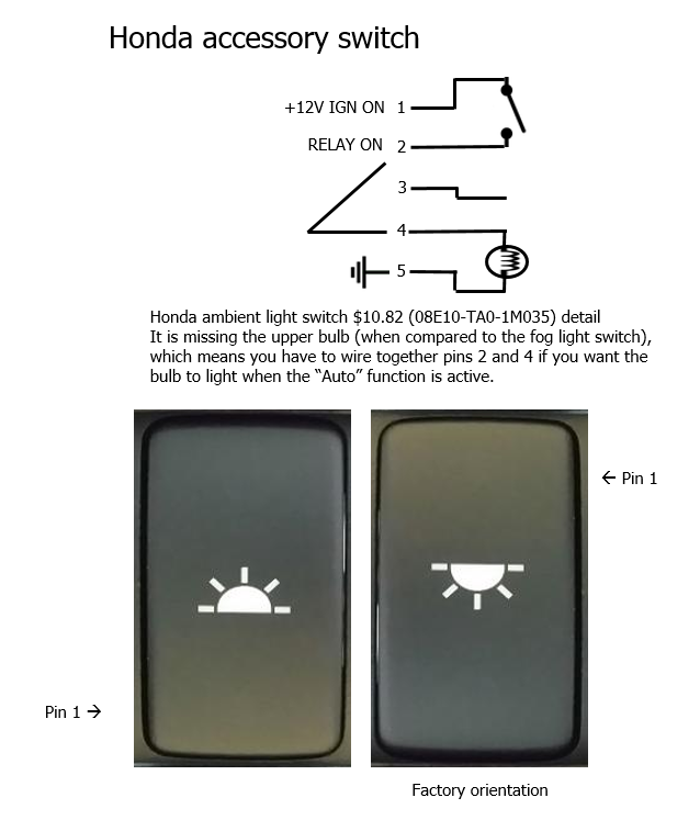
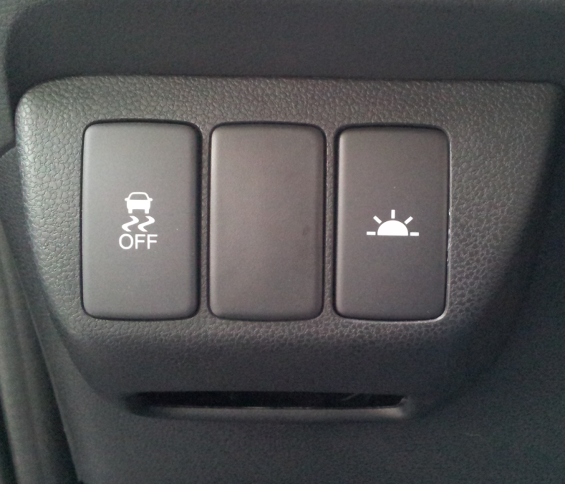
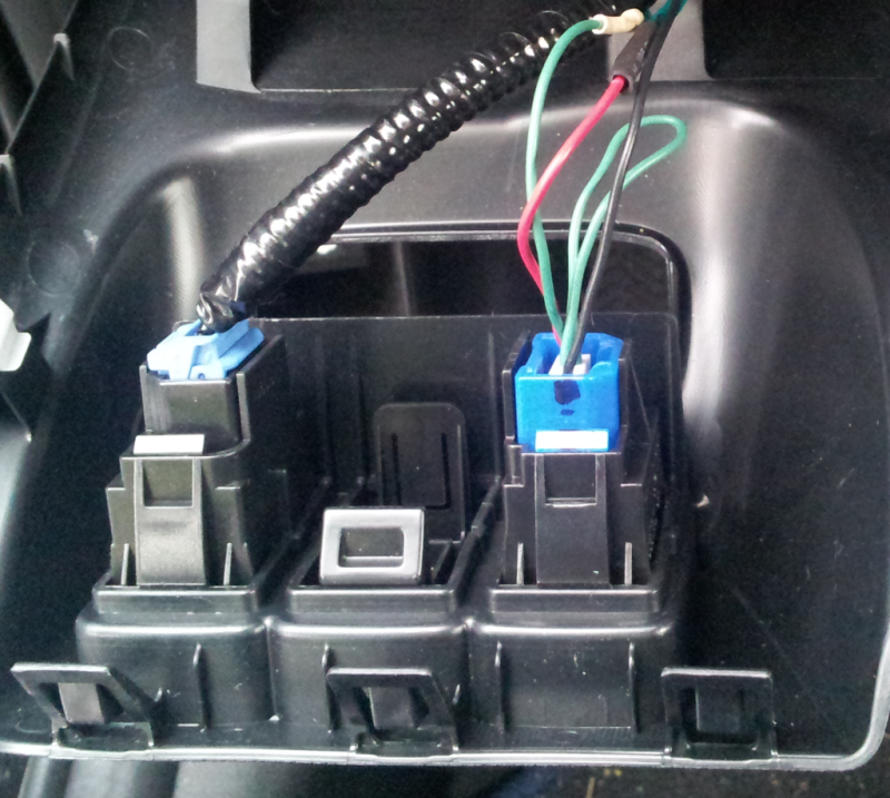
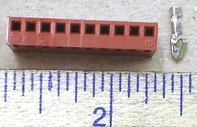
I used an accessory ambient light switch mounted inverted as the �Auto� enable switch. The circuit is powered by an add-a-circuit plug inserted in the fuse box in the daytime running light fuse position (on when the key is in the ON position). I wired the switch as shown so that the bulb in the switch is on whenever the Auto switch is enabled. I used a Molex tenth inch spacing connector I found at my local Frys to connect to the switch (I trimmed down a 10-pin connector to 5 pins because that was what they had in stock).
I tapped into the headlight circuit of the Fit at the headlight switch. I opened the steering column cover and unplugged the upper headlight switch connector. Using the wiring diagram from the Fit manual, I traced the red wire in the connector to be the "headlight on" wire. This wire is connected to ground when the headlight switch is in the full on position. I tapped this wire so my circuit could also pull this signal to ground.
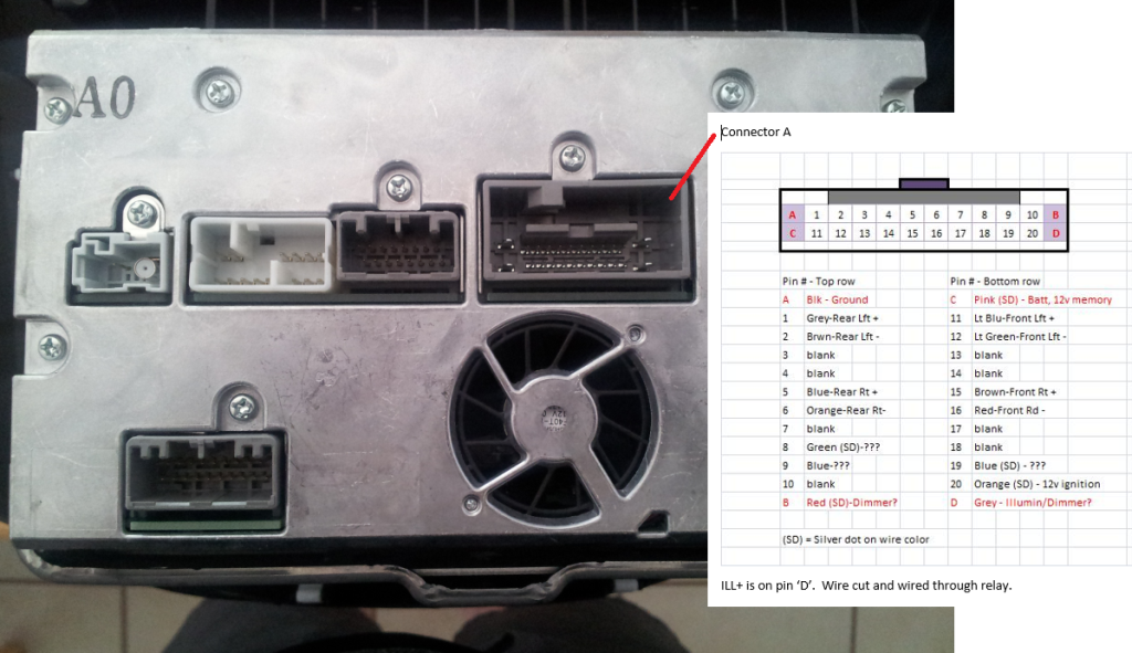
I like my headlights on in the twilight hours for my commute, but I often found the Nav unit to be too dark to see in this transitional part of the day. I solved the problem by allowing my circuit to break the illumination signal to the Nav unit unless the light level was low enough that I wanted it to switch into night mode. The image of the back of the Nav unit shows that connector A (the one with 4 larger pins at the corners) has the illumination signal at position �D�. The wire at this position is gray. I simply cut the wire in the harness an inch behind the connector, and soldered an extension wire pair to the two cut ends. In this way, I was able to wire the illumination wire through my relay contact.
The Software
If you have not used the Arduino development environment before, check out the Getting Started tutorials on the Adafruit site (http://learn.adafruit.com/introducin...et/guided-tour). The programming environment uses �sketches� (mine is below) to program the device. The code is broken into two main parts: setup and loop. The instructions in setup are run one time when the trinket is powered up. The instructions in the loop run repeatedly until power is removed.
In my setup function, I configure the pins as inputs and outputs and set the initial state of the output pins. In my loop instructions, I read the value of the LDR voltage and decide to turn the outputs on or off. The loop code does two other things that are easy to do in code, but would be a bit harder in a dedicated circuit: hysteresis and low-pass filtering.
Hysteresis simply means that two different levels are used for the turn-on and turn-off decision. This prevents the circuit from getting into a situation of rapidly turning the lights on and off when the light level is near a single threshold.
The software also applies a low-pass filter for the LDR light level so rapid changes in the light level do not cause rapid changes in the output state. An example of this would be driving next to a series of trees when the sun is low on the horizon. The sunlight on your dash can �strobe� as you pass through the tree shadows. The exponential low pass filter in my code keeps the code size small because it does not require the trinket to use its floating point library. If you filter too much (using a smaller alpha value) the circuit will be slow to react to changing light conditions. If you filter too little, the circuit will overreact to small fluctuations of the light level. The values in my code seem to work well and similar to my auto headlight feature in my other car (an Accord).
In my code, the loop runs about 4 times a second. If you change this, you may need to adjust the filter parameters to compensate. If you decide that you don�t like the levels where the headlights or Nav illumination switch on, simply modify the LIGHTS_ON_VAL or NAV_ILL_ON_VAL constants near the top of the code. You can reprogram your trinket as often as you want. There are unused i/o pins on the trinket, so you could expand this circuit to add other features.
ldr.ino (my trinket sketch file)
The Hardware
I based the design on a very small Arduino processer, the Adafruit Trinket (Adafruit Trinket - Mini Microcontroller - 5V Logic ID: 1501 - $6.95 : Adafruit Industries, Unique & fun DIY electronics and kits). It only costs about $7 and requires nothing more than a mini-B USB cable and some free software downloaded from Adafruit for your PC to program it. Once programmed, the trinket acts as a dedicated circuit (no need to keep a PC connected). My circuit design is based on some examples using a light dependent resistor (LDR) on the Adafruit website. I purchased most of the electronic parts from Adafruit, but you can also get them from Digikey/Mouser/etc. The circuit samples the value of the LDR and decides to put out a 1 (5V) or a 0 (0V) based on the current light level. The trinket�s low current outputs are used to drive transistors, which in turn can drive enough current to switch on a 12V relay. Separate outputs are used for the headlight function and Nav illumination function so they can be switched at different light levels. The LDR is part of a voltage divider on input 2 of the trinket. As the light level goes up, the resistance of the LDR goes down, causing the voltage level on pin 2 to go up. The LDR for this circuit is attached to a longer wire pair (about 3ft), so the LDR can be located on the dash while the rest of the circuit is installed near the fuse box. I did not drill any holes for this install. I simply placed the LDR on the driver�s side of the joint of the center dash section (I removed it to get to get the Nav unit out). I used a bit of electrical tape on the wire to the LDR to keep it in place as I re-installed the center dash section. You can barely see the sensor after the dash is re-assembled. I included a Molex connector on the wires going into my circuit box so I could easily unplug and remove it from the vehicle when I wanted to adjust the program.
I used an accessory ambient light switch mounted inverted as the �Auto� enable switch. The circuit is powered by an add-a-circuit plug inserted in the fuse box in the daytime running light fuse position (on when the key is in the ON position). I wired the switch as shown so that the bulb in the switch is on whenever the Auto switch is enabled. I used a Molex tenth inch spacing connector I found at my local Frys to connect to the switch (I trimmed down a 10-pin connector to 5 pins because that was what they had in stock).
I tapped into the headlight circuit of the Fit at the headlight switch. I opened the steering column cover and unplugged the upper headlight switch connector. Using the wiring diagram from the Fit manual, I traced the red wire in the connector to be the "headlight on" wire. This wire is connected to ground when the headlight switch is in the full on position. I tapped this wire so my circuit could also pull this signal to ground.
I like my headlights on in the twilight hours for my commute, but I often found the Nav unit to be too dark to see in this transitional part of the day. I solved the problem by allowing my circuit to break the illumination signal to the Nav unit unless the light level was low enough that I wanted it to switch into night mode. The image of the back of the Nav unit shows that connector A (the one with 4 larger pins at the corners) has the illumination signal at position �D�. The wire at this position is gray. I simply cut the wire in the harness an inch behind the connector, and soldered an extension wire pair to the two cut ends. In this way, I was able to wire the illumination wire through my relay contact.
The Software
If you have not used the Arduino development environment before, check out the Getting Started tutorials on the Adafruit site (http://learn.adafruit.com/introducin...et/guided-tour). The programming environment uses �sketches� (mine is below) to program the device. The code is broken into two main parts: setup and loop. The instructions in setup are run one time when the trinket is powered up. The instructions in the loop run repeatedly until power is removed.
In my setup function, I configure the pins as inputs and outputs and set the initial state of the output pins. In my loop instructions, I read the value of the LDR voltage and decide to turn the outputs on or off. The loop code does two other things that are easy to do in code, but would be a bit harder in a dedicated circuit: hysteresis and low-pass filtering.
Hysteresis simply means that two different levels are used for the turn-on and turn-off decision. This prevents the circuit from getting into a situation of rapidly turning the lights on and off when the light level is near a single threshold.
The software also applies a low-pass filter for the LDR light level so rapid changes in the light level do not cause rapid changes in the output state. An example of this would be driving next to a series of trees when the sun is low on the horizon. The sunlight on your dash can �strobe� as you pass through the tree shadows. The exponential low pass filter in my code keeps the code size small because it does not require the trinket to use its floating point library. If you filter too much (using a smaller alpha value) the circuit will be slow to react to changing light conditions. If you filter too little, the circuit will overreact to small fluctuations of the light level. The values in my code seem to work well and similar to my auto headlight feature in my other car (an Accord).
In my code, the loop runs about 4 times a second. If you change this, you may need to adjust the filter parameters to compensate. If you decide that you don�t like the levels where the headlights or Nav illumination switch on, simply modify the LIGHTS_ON_VAL or NAV_ILL_ON_VAL constants near the top of the code. You can reprogram your trinket as often as you want. There are unused i/o pins on the trinket, so you could expand this circuit to add other features.
ldr.ino (my trinket sketch file)
HTML Code:
// defines

#define ON              (HIGH)
#define OFF             (LOW)

#define HYSTERESIS      (10)
#define LIGHTS_ON_VAL   (930)
#define NAV_ILL_ON_VAL  (330)

#define LIGHTS_OFF_VAL  (LIGHTS_ON_VAL + HYSTERESIS)
#define NAV_ILL_OFF_VAL (NAV_ILL_ON_VAL + 2*HYSTERESIS)

boolean  lights = OFF;  // init the headlight output state
boolean  navOut = OFF;  // init the nav illumination output state
uint16_t loopCount = 0;
uint16_t ldr = LIGHTS_ON_VAL;

uint8_t lightRelay = 1;   // output connected to relay for headlights
uint8_t navOutput  = 4;   // ouptut connected to relay for nav illumination (also board LED)

// use a fixed point exp filter to smooth, filter constant alpha is alpha64/64
uint16_t expSmooth64(uint16_t newVal, uint16_t currVal, uint8_t alpha64)
{
    uint32_t filterVal = ((uint32_t)currVal * (64 - alpha64)) + (alpha64 * newVal);
    return (uint16_t)(filterVal >> 6);
}

void setup()
{
    pinMode(2, INPUT);     // set pin 2 (A1) as input
    digitalWrite(2, LOW);  // turn off internal pull-up for A1

    // initialize the digital outputs
    pinMode(lightRelay, OUTPUT);
    pinMode(navOutput, OUTPUT);

    // set both outputs to low initially
    digitalWrite(lightRelay, LOW);
    digitalWrite(navOutput,  LOW);
}

void loop()
{
    // LDR is connected to #A1, 10-bit range (0-1023)
    ldr = expSmooth64(analogRead(1), ldr, 3);

    if (lights == ON)
    {
        if (ldr > LIGHTS_OFF_VAL) // LDR val is above OFF limit
        {
            lights = OFF;  // turn the lights off
        }
    }
    else
    {
        if (ldr < LIGHTS_ON_VAL)  // LDR val is below ON limit
        {
            lights = ON;   // turn the lights on
        }
    }
    digitalWrite(lightRelay, lights);

    if (navOut == ON)
    {
        if (ldr > NAV_ILL_OFF_VAL) // LDR val is above OFF limit
        {
            navOut = OFF;  // turn the nav illumination off
        }
    }
    else
    {
        if (ldr < NAV_ILL_ON_VAL)  // LDR val is below ON limit
        {
            navOut = ON;   // turn the nav illumination on
        }
    }
    digitalWrite(navOutput, navOut);

    delay(250);  // repeat every 1/4 second
    loopCount++; // will roll over about every 4.5 hours
}
#2
09-05-2014, 03:59 PM

AWESOME!!!
If I decided to implement that in my car, sure I'll contact you.
I think a picture of your car and the LDR sensor is missing.
Luis
Honda Fit Sport - Blue
If I decided to implement that in my car, sure I'll contact you.
I think a picture of your car and the LDR sensor is missing.
Luis
Honda Fit Sport - Blue
Last edited by luismycorreo; 09-05-2014 at 04:08 PM.
#3
09-05-2014, 04:27 PM
Here are a couple of pics of the LDR position.
Last edited by tangoVictor; 09-05-2014 at 04:30 PM.
#4
09-05-2014, 04:35 PM

Nice first post. 
I heard about those Arduino's and their capabilities.... I think there's also an aftermarket unit that does the auto headlights, but from what I heard that unit has glitches.
Nice mod!
I heard about those Arduino's and their capabilities.... I think there's also an aftermarket unit that does the auto headlights, but from what I heard that unit has glitches.
Nice mod!
#5
09-06-2014, 11:00 PM

Bixenon question
I may be going out on a limb, but my 2012 fit sport has no high beams since removing the drl fuse,would like to have high beam function back,h4 bulb for all functions makes this tricky. 2011 back MICU does not kill high beams when drl fuse is removed.do you have a fix for this?
#6
09-07-2014, 03:03 PM
#7
09-12-2014, 08:03 PM
Question:
Where did you get that blue connector for the switch?
Do you have the Honda Part number?

Luis
Where did you get that blue connector for the switch?
Do you have the Honda Part number?
Luis
Last edited by luismycorreo; 09-12-2014 at 08:08 PM.
#8
09-13-2014, 04:47 PM
The blue plastic is part of the Honda switch (08E10-TA0-1M035). The connector is only the white part that appears inside the blue part. It is a Molex 0.1" spacing connector that I show in my pics.
#9
09-13-2014, 05:30 PM
How is the fitment??
Luis

Thread
Thread Starter
Forum
Replies
Last Post
Super Mario
Fit DIY: Repair & Maintenance
0
07-06-2015 06:56 PM
CBCgirl
2nd Generation (GE 08-13)
7
10-30-2009 09:46 PM
FikseRxSeven
Fit Interior & Exterior Illumination
3
08-19-2006 09:45 AM