Samco Hose, Maxbore Throttle Body, Boomslang Harness
#1
Samco Hose, Maxbore Throttle Body, Boomslang Harness
Last weekend was a very productive weekend for my Honda Fit and I 
Samco Hose both Coolant and Breather hose kit installed along with the Samco clamp kit, complete story:
Hose just arrived from UK:


GReddy Temperature Sensor Adapter just arrived from Japan:

Lisle Hose Pry tool kit from Summit Racing just arrive:

First step, drain the radiator coolant:

Take a last look before going yellow

Airbox removed, STOCK Throttle body next:

Removing connector and hoses from stock throttle body:

There is one hidden bolt on the lower side of the throttle body:

Remove 4 bolts holding the throttle body:

Throttle body comparison, stock and Maxbore modified version:
(Maxbore enlarge, port polish, gasket match a brand new OEM throttle body that I sent to him)

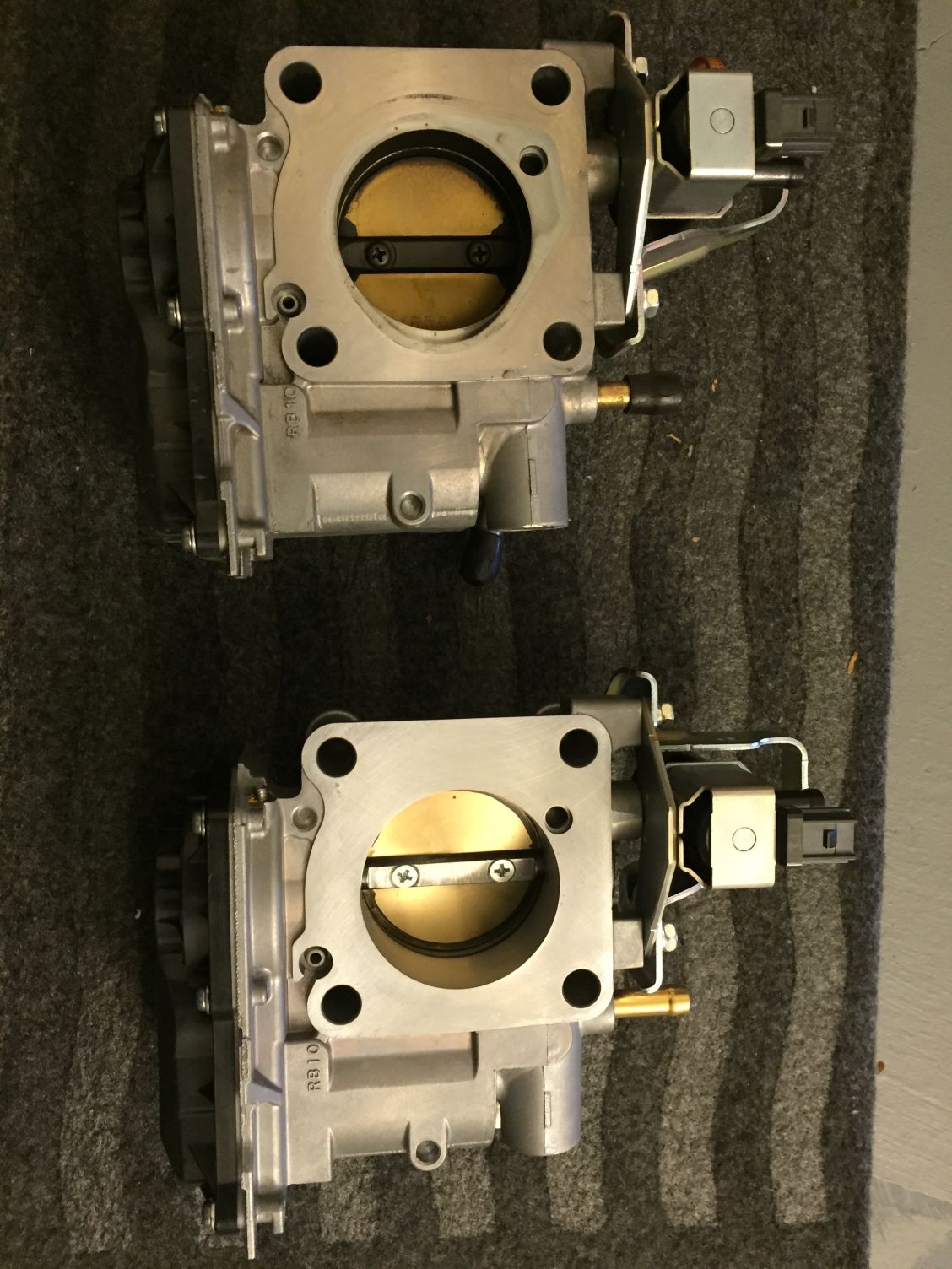
Plug the holes for coolant throttle body heater function on the Maxbore one:

Transfer wire clip from the old throttle body to the new one:

Next step start taking out the old hoses with Lisle Pick tools,
trust me, you don't want to do it without this tools !!!

Taking out the clip holding the hoses with screwdriver...
oh this 2 hoses that connect to the firewall is the most hardest to take out due to their position on the firewal...
my arm got a lot of scratch to proof

Install new hose with the Samco hose clamp:


Checking the position for the GReddy temperature sensor adapter:

ok, moment of truth, sawing my brand new Samco hose... uhhhh....:

GReddy installed:


to be continued:

Samco Hose both Coolant and Breather hose kit installed along with the Samco clamp kit, complete story:
Hose just arrived from UK:


GReddy Temperature Sensor Adapter just arrived from Japan:

Lisle Hose Pry tool kit from Summit Racing just arrive:

First step, drain the radiator coolant:

Take a last look before going yellow


Airbox removed, STOCK Throttle body next:

Removing connector and hoses from stock throttle body:

There is one hidden bolt on the lower side of the throttle body:

Remove 4 bolts holding the throttle body:

Throttle body comparison, stock and Maxbore modified version:
(Maxbore enlarge, port polish, gasket match a brand new OEM throttle body that I sent to him)


Plug the holes for coolant throttle body heater function on the Maxbore one:

Transfer wire clip from the old throttle body to the new one:

Next step start taking out the old hoses with Lisle Pick tools,
trust me, you don't want to do it without this tools !!!

Taking out the clip holding the hoses with screwdriver...
oh this 2 hoses that connect to the firewall is the most hardest to take out due to their position on the firewal...
my arm got a lot of scratch to proof


Install new hose with the Samco hose clamp:


Checking the position for the GReddy temperature sensor adapter:

ok, moment of truth, sawing my brand new Samco hose... uhhhh....:

GReddy installed:


to be continued:
#2
Now its time for installing throttle body back:

Lucky there is a hole ready for bolts to thread,
so I used it to hang the DEFI Boost Gauge Sensor,
it's the small black box with DEFI name on top,


I also install the DEFI Temperature sensor on the GReddy:

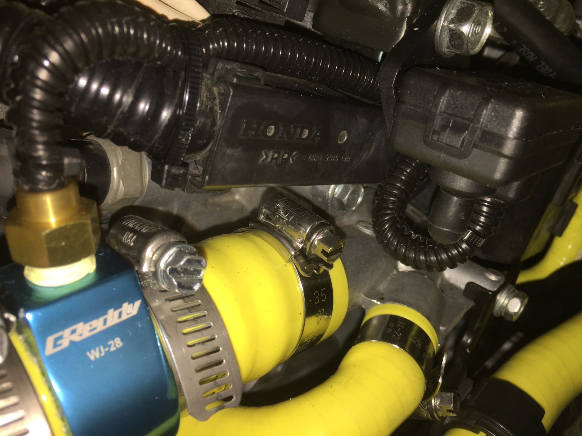
Notice how I wrap each sensor cable with black wire loom than tie lock and route it so it looks like it came from factory like that...well if there is a car from factory came with Yellow Hose that is
to be continued:

Lucky there is a hole ready for bolts to thread,
so I used it to hang the DEFI Boost Gauge Sensor,
it's the small black box with DEFI name on top,


I also install the DEFI Temperature sensor on the GReddy:


Notice how I wrap each sensor cable with black wire loom than tie lock and route it so it looks like it came from factory like that...well if there is a car from factory came with Yellow Hose that is

to be continued:
#3
Boomslang Harness time:
So I now have so many wires and hose that I must pass through the firewall, I could not possibly jam them on the existing rubber grommet that pass current factory wiring since it might broke the factory cable or leak rain water/noise some fume etc...
so I decided I need to drill a new hole on the firewall and put new rubber grommet...
Unfortunately there is either small area that can be drilled or an A/C blower or other stuff on the interior side block the opening...
so I look for alternative area...
suddenly I see a BIG BIG LARGE HOLES from the passenger side inner engine compartment wall that connect it inside the passenger/right side fender and it also protected from the debris by the plastic fender liner...
which then could connect to the right most corner of the firewall...
Here is that big holes:

I need to check what is behind that firewall area, so I took out the glove box and I see an area without any obstruction:

so I took out the plastic fender liner:

Get my Makita, Titanium Drill bit for pilot holes and my firewall hole drill bit

and here are the holes that I just drilled,
I made one round holes at the top (for All Defi sensor wiring and extra wiring that I lay in preparation for future LED headlight/DRL/Setrab Fan Cooled Oil coller mode),
one oval holes on the center for Boomslang Wiring Harness with Honda Factory OEM Grommet
on larger round holes for future wiring of Defi Fuel Pressure, Oil Pressure and Temp sensor in the future,
and one smaller round on the bottom for Samco hose Vacuum tube to AEM F/IC onboard MAP sensor from Sprintex Supercharger

Then I paint it with Primer and Top Coat paint to prevent rust:

to be continued:
So I now have so many wires and hose that I must pass through the firewall, I could not possibly jam them on the existing rubber grommet that pass current factory wiring since it might broke the factory cable or leak rain water/noise some fume etc...
so I decided I need to drill a new hole on the firewall and put new rubber grommet...
Unfortunately there is either small area that can be drilled or an A/C blower or other stuff on the interior side block the opening...
so I look for alternative area...
suddenly I see a BIG BIG LARGE HOLES from the passenger side inner engine compartment wall that connect it inside the passenger/right side fender and it also protected from the debris by the plastic fender liner...
which then could connect to the right most corner of the firewall...
Here is that big holes:

I need to check what is behind that firewall area, so I took out the glove box and I see an area without any obstruction:

so I took out the plastic fender liner:

Get my Makita, Titanium Drill bit for pilot holes and my firewall hole drill bit


and here are the holes that I just drilled,
I made one round holes at the top (for All Defi sensor wiring and extra wiring that I lay in preparation for future LED headlight/DRL/Setrab Fan Cooled Oil coller mode),
one oval holes on the center for Boomslang Wiring Harness with Honda Factory OEM Grommet
on larger round holes for future wiring of Defi Fuel Pressure, Oil Pressure and Temp sensor in the future,
and one smaller round on the bottom for Samco hose Vacuum tube to AEM F/IC onboard MAP sensor from Sprintex Supercharger

Then I paint it with Primer and Top Coat paint to prevent rust:

to be continued:
#4
Now
I remember I had a used door rubber lining lying around,
so I cut it to around 25cm then use it around the sharp edges of the large holes to protect the wiring further:

see how I put it on the holes:

I also had a used rubber grommet for door that I slide out and then slide into boomslang wire harness that will fit the oval holes perfectly:

Then I use round rubber grommet for the other wiring and Samco vacuum hose tube, plus I use a PLUG for the extra holes that I do not use right now but ready for future Defi gauge upgrade:

I remember I had a used door rubber lining lying around,
so I cut it to around 25cm then use it around the sharp edges of the large holes to protect the wiring further:

see how I put it on the holes:

I also had a used rubber grommet for door that I slide out and then slide into boomslang wire harness that will fit the oval holes perfectly:

Then I use round rubber grommet for the other wiring and Samco vacuum hose tube, plus I use a PLUG for the extra holes that I do not use right now but ready for future Defi gauge upgrade:

#5
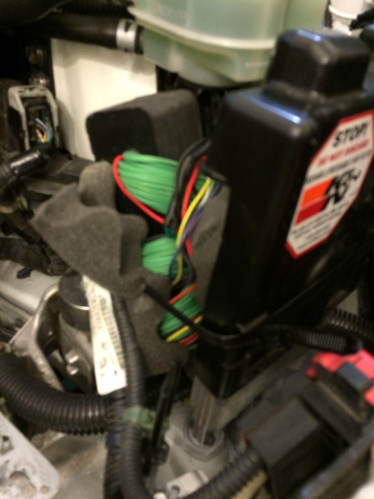
Here is how I connect the Boomslang MASSIVE wiring harness block,
I put in between the factory ECU and the brake fluid reservoir,
it's size and the hundreds of wire actually make it tight and then I put
and extra large tie lock to further secure it.
I run the main wiring of the Boomslang harness back to AEM F/IC-6 using the Garage Kuo's strut tower bar as the mounting point, secure it with many tie locks... it is really safe and secure.


Oh this is how I temporarily store the rest of the Vacuum hose for now until I install the Sprintex supercharger:

and this is how it came out from the firewall to behind the glove box:


I put in between the factory ECU and the brake fluid reservoir,
it's size and the hundreds of wire actually make it tight and then I put
and extra large tie lock to further secure it.
I run the main wiring of the Boomslang harness back to AEM F/IC-6 using the Garage Kuo's strut tower bar as the mounting point, secure it with many tie locks... it is really safe and secure.


Oh this is how I temporarily store the rest of the Vacuum hose for now until I install the Sprintex supercharger:

and this is how it came out from the firewall to behind the glove box:


#6
I drill several holes inside the upper glove box, the rectangular one on the left side for all the boomslang wiring harness and all current DEFI wiring harness, the small round one with round rubber grommet for the vacuum hose feeding the AEM-F/IC-6 MAP sensor is the one I most proud of 
It looks like it is there from factory


Here is how the upper glove box look with both Defi and AEM F/IC-6 in there:

It was a tight fit, but the glove box door closes without a problem...
oh and I custom leather cover this glove box with yellow stitching and Audi Supercharged badge borrowed for a Honda Fit
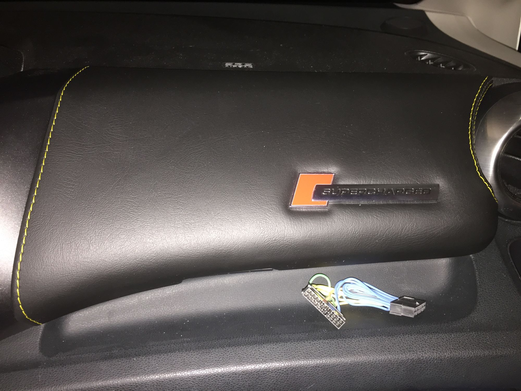

It looks like it is there from factory


Here is how the upper glove box look with both Defi and AEM F/IC-6 in there:

It was a tight fit, but the glove box door closes without a problem...
oh and I custom leather cover this glove box with yellow stitching and Audi Supercharged badge borrowed for a Honda Fit


Last edited by BMW ALPINA; 05-31-2016 at 07:22 PM.
#7
But, I still have problem...
when I connect the AEM and start the engine,
immediately I got OBD error code P2649.
This error code means the VTEC system malfunction.
I custom order the Boomslang wiring harness with VTEC activation wiring connected to the AEM F/IC-6...
Little that I know that it mean bypasing the connection between ECU and VTEC solenoid causing factory ECU to think something wrong with the VTEC solenoid...
I have not test drive my car so I don't know if this will make the car goes into limp mode,
but even if it is not, I can not have it this way because
turn out the this OBD code also cause the VSA system to malfunction with VSA light comes on all the time...
I think there are 2 solutions...
the most certain one is buy another vtec solenoid and connect it to ECU just so ECU think it connect with a VTEC solenoid even though the VTEC solenoid is not installed on the engine but just doing nothin...
I had talk to Boomslang and he said he need to send me a pigtail wire so I can insert it into the boomslang connector that connect to the ECU...
second solution and cheaper way (if it work) is to connect both AEM F/IC and factory ECU to the current working VTEC solenoid but put a DIODE so the signal from AEM would not go to factory ECU while the signal from factory ECU do not go to AEM
but both of them can send signal to VTEC solenoid.
I figure the one which really will control still the AEM because it will have lower VTEC activation point compare to factory ECU...
so for now, I just disconnect the boomslang harness and AEM and just use the factory ECU again...
right away all OBD error engine light and VSA gone and return to normal...
I still need to get the ECU to learn the NEW Maxbore throttle body but I still could not figure out
how to get my HIM (GNA 600) module to work with the ecu and reset it...
so this is still a journey

#8
Ok,... This is what I figure will trick the ECU so I can lower the VTEC activation using AEM F/IC-6 without any check engine light...
Connect ECU VTEC Activation wire to Trigger Wire on Relay#1
Relay#1 will have power input directly from Battery 12Volts
Relay#1 Normally Open output will be connected with the VTEC Solenoid
The same output will also power the Trigger Wire on Relay#2
Relay#2 will be wired as Normally CLOSED.
Relay#2 will have it's input connected to Ground
Relay#2 Normally CLOSED output will be connected to the ECU wire that supposedly goes to the VTEC Oil Pressure Switch so basically
the ECU will never see the VTEC Oil Pressure Switch again. (unless I remove the boomslang wiring harness and connect the stock car harness directly to the ECU again.)
Please note that all this wire modification is done on the boomslang harness so no factory stock harness is cut or tap...
I will also prepare jumper switch just in case I want to by passed the relay and back to non early VTEC activation.
Here is what I predict will happened...
AEM F/IC-6 trigger early VTEC activation for example at 4,000 rpm.
ECU do not see any changes because it's output to solenoid is now isolated to relay and it's input to oil pressure switch is still grounded by the normally closed relay#2
When engine hit 5,400 rpm, the ECU now will try to activate the solenoid by energizing the trigger on relay#1 which will "click" simulating a VTEC solenoid taking current and also activating relay#2 to OPEN the ground so the ECU now "see" that the oil pressure switch just goes to open position...
I am still assembling all the parts and hopefully I am done tomorrow so I can test this relay circuit... if it's work then I can move to the next step which is.... INSTALLING MY SPRINTES
Here is the Hella Relay with Hella Water Proof Harness:

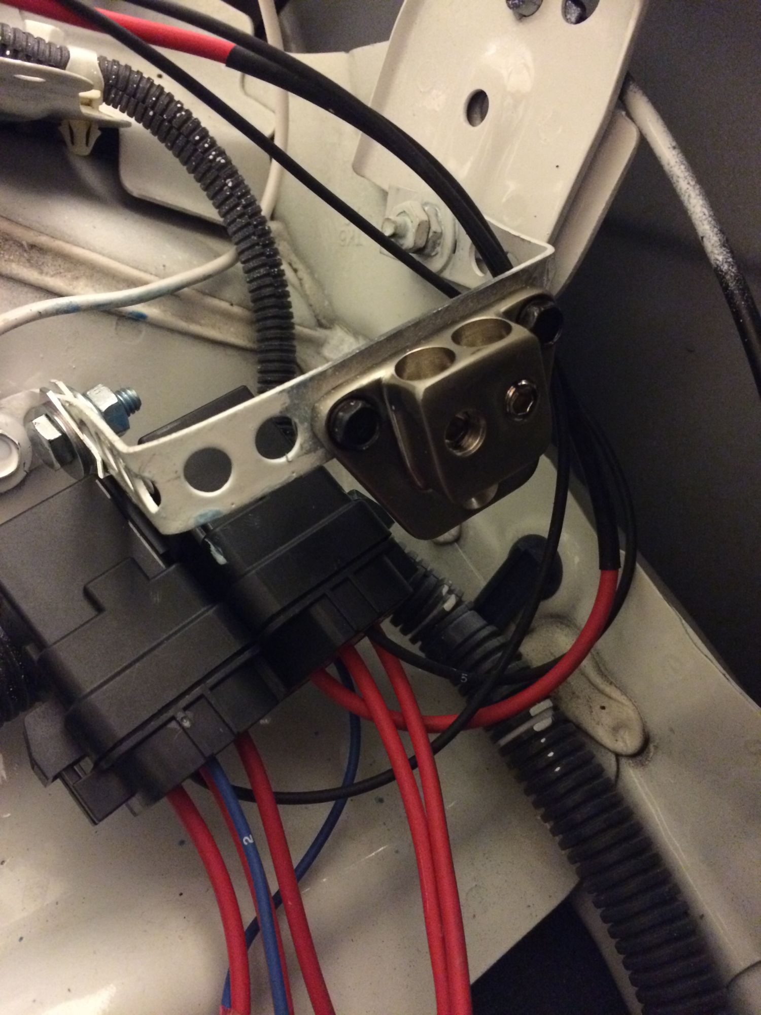
Making the Bracket for relay, and this Bracket will also serve as Ground Bar where I also install MTX StreetWires GT24 Dual 4 AWG Ground Terminal
Here is a PERFECT place for the Relay Bracket, just beside the ECU:
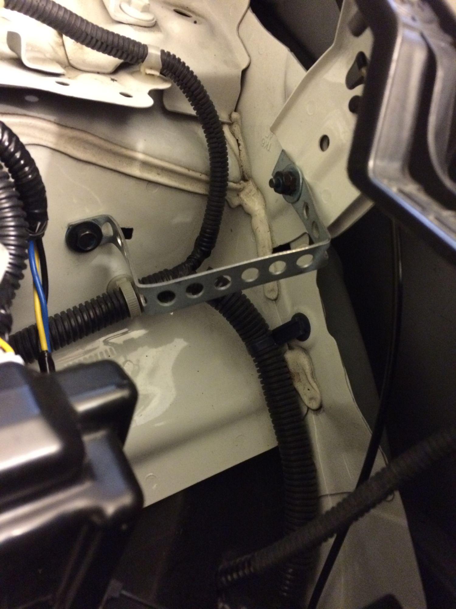
Relay and Ground Terminal Installed on the bracket:
While I do this, I also upgrade my single fuse holder.
This old Rockford Fosgate single fuse holder that I have was or my old Rockford Fosgate powered sub-woofer that I no longer have.

I remove that old Rockford Fosgate single Fuse holder
and replace it with Scosche EFXFDBUQM 0/4-4/8GA Quad Mini-ANL Distribution Block.

I need 4 output for future upgrade and the current relay circuit.
so the output1 will be for relay
output2 will be for the upcoming Setrab Oil Cooler Fan and VLED Switch Back DRL/Turn Signal (when I upgrade headlight and fog light to IPF LED bulb)
output3 will be for the 2 under seat Pioneer Subwoofer (future upgrade)
output4 will be for the Zapco amp and dsp located on the trunk (future upgrade)
I modify the previous bracket added reinforcement bar to hold this much larger fuse distribution block securely, the location remain the same just forward of the battery where the bracket bolt to the base of the battery holder:


I am so tired now, so I will continue working tomorrow
Connect ECU VTEC Activation wire to Trigger Wire on Relay#1
Relay#1 will have power input directly from Battery 12Volts
Relay#1 Normally Open output will be connected with the VTEC Solenoid
The same output will also power the Trigger Wire on Relay#2
Relay#2 will be wired as Normally CLOSED.
Relay#2 will have it's input connected to Ground
Relay#2 Normally CLOSED output will be connected to the ECU wire that supposedly goes to the VTEC Oil Pressure Switch so basically
the ECU will never see the VTEC Oil Pressure Switch again. (unless I remove the boomslang wiring harness and connect the stock car harness directly to the ECU again.)
Please note that all this wire modification is done on the boomslang harness so no factory stock harness is cut or tap...
I will also prepare jumper switch just in case I want to by passed the relay and back to non early VTEC activation.
Here is what I predict will happened...
AEM F/IC-6 trigger early VTEC activation for example at 4,000 rpm.
ECU do not see any changes because it's output to solenoid is now isolated to relay and it's input to oil pressure switch is still grounded by the normally closed relay#2
When engine hit 5,400 rpm, the ECU now will try to activate the solenoid by energizing the trigger on relay#1 which will "click" simulating a VTEC solenoid taking current and also activating relay#2 to OPEN the ground so the ECU now "see" that the oil pressure switch just goes to open position...
I am still assembling all the parts and hopefully I am done tomorrow so I can test this relay circuit... if it's work then I can move to the next step which is.... INSTALLING MY SPRINTES

Here is the Hella Relay with Hella Water Proof Harness:

Making the Bracket for relay, and this Bracket will also serve as Ground Bar where I also install MTX StreetWires GT24 Dual 4 AWG Ground Terminal
Here is a PERFECT place for the Relay Bracket, just beside the ECU:

Relay and Ground Terminal Installed on the bracket:

While I do this, I also upgrade my single fuse holder.
This old Rockford Fosgate single fuse holder that I have was or my old Rockford Fosgate powered sub-woofer that I no longer have.

I remove that old Rockford Fosgate single Fuse holder
and replace it with Scosche EFXFDBUQM 0/4-4/8GA Quad Mini-ANL Distribution Block.

I need 4 output for future upgrade and the current relay circuit.
so the output1 will be for relay
output2 will be for the upcoming Setrab Oil Cooler Fan and VLED Switch Back DRL/Turn Signal (when I upgrade headlight and fog light to IPF LED bulb)
output3 will be for the 2 under seat Pioneer Subwoofer (future upgrade)
output4 will be for the Zapco amp and dsp located on the trunk (future upgrade)
I modify the previous bracket added reinforcement bar to hold this much larger fuse distribution block securely, the location remain the same just forward of the battery where the bracket bolt to the base of the battery holder:


I am so tired now, so I will continue working tomorrow
Last edited by BMW ALPINA; 07-03-2016 at 01:29 AM.
#9
Ok, so I continue today...
Here are the relays with Ground Distribution Block wiring connected:

Time to cut the boomslang wiring harness to intercept:
Here are the wires that (I cut) connect the ECU to the Oil Pressure Switch,
it is on Connector C Pin 22 (C22):

Now, I am cutting wire at Connector B pin 35 (B35) that connect the ECU to the VTEC solenoid:

I use MOLEX connector so I can quickly take the boomslang harness out and get back to stock, or just in case, I don't want to use the relay anymore, I can just plug in a MOLEX plu that act as a jumper:

Now, it's time to connect the relay Common terminal (Input) with the 12Volts source from the EFX Fuse Distribution Block:

Here is the Molex female and male connector connected:

Here is the boomslang wiring harness safely secure and tuck tight between the ECU:
I start the car, and NO Error code despite the ECU do not connect directly to VTEC solenoid...
so the internal resistance in the relay actually trick the ECU into thinking it is connected to the VTEC solenoid but in fact it is connected to the relay trigger.
First phase pass...
Second Phase will be driving the car on the road and see if the VTEC activate ok with no error at 5,400 rpm (stock activation point).
After that (if I pass),
then I go to Third Phase which is using AEM to lower VTEC activation point to around 5,000 rpm. if it work then I don't have to buy K-Tuner to lower my VTEC activation point
Ok, about to test drive the car now (Second Phase)...
Here are the relays with Ground Distribution Block wiring connected:

Time to cut the boomslang wiring harness to intercept:
Here are the wires that (I cut) connect the ECU to the Oil Pressure Switch,
it is on Connector C Pin 22 (C22):

Now, I am cutting wire at Connector B pin 35 (B35) that connect the ECU to the VTEC solenoid:

I use MOLEX connector so I can quickly take the boomslang harness out and get back to stock, or just in case, I don't want to use the relay anymore, I can just plug in a MOLEX plu that act as a jumper:

Now, it's time to connect the relay Common terminal (Input) with the 12Volts source from the EFX Fuse Distribution Block:

Here is the Molex female and male connector connected:

Here is the boomslang wiring harness safely secure and tuck tight between the ECU:

I start the car, and NO Error code despite the ECU do not connect directly to VTEC solenoid...
so the internal resistance in the relay actually trick the ECU into thinking it is connected to the VTEC solenoid but in fact it is connected to the relay trigger.
First phase pass...
Second Phase will be driving the car on the road and see if the VTEC activate ok with no error at 5,400 rpm (stock activation point).
After that (if I pass),
then I go to Third Phase which is using AEM to lower VTEC activation point to around 5,000 rpm. if it work then I don't have to buy K-Tuner to lower my VTEC activation point

Ok, about to test drive the car now (Second Phase)...

#10
Do a test run, it run well, no error code when the rev are climbing fast past the VTEC activation point, but when I stay around the rpm where VTEC activated, I got into limp mode again...
so I literally goes back to the drawing board and drawing on piece of paper how my Relay Circuit look like...
Suddenly I realized, I need a diode to BLOCK the AEM F/IC-6 VTEC signal from going to Relay#2 and trigger the oil pressure switch open signal to ECU...
no wonder I got OBD 2627...
so tomorrow I am going to install the diode...
I should have draw my circuit properly so I can see the problem right away...
my initial sketch drawing was done in a hurry and with my head dizzy from the fume of the paint (painting Sprintex)... oh well...
#12
Test Drive the car again, set the AEM F/IC-6 to activate the VTEC Solenoid at 5,000 rpm for now,
and... SUCCESS !!!
No more OBD error code, the ECU never knew that the VTEC had been
activated lower than 5,400 rpm !!!
So for anyone interested in doing this modification,
here are the diagram:

and... SUCCESS !!!
No more OBD error code, the ECU never knew that the VTEC had been
activated lower than 5,400 rpm !!!
So for anyone interested in doing this modification,
here are the diagram:

#14
I still have to do several more steps before I can install my Sprintex...
like, install Denso Fuel Pump and see if I need a return fuel line/Fuel Pressure Regulator,
then another relay circuit to activate Map B on AEM F/IC-6 while have a Honda OEM switch with light indicator activating it...
Change to IK-24 spark plug, and several other minor details...
How about your K20 engine swap project?
Have you finish the engine swap project?
I am sure it's going to be awesome

#16
The Pressure.... don't know too, but the spec on the Honda Service Manual specify it work fine if working pressure between 48 to 54psi.
Mine is around 48-50psi right now.
Some people with Manual Transmission Car and Sprintex with the 5th injector configuration have problem with lack of fuel at high rpm...
Church Tuning also recommend them to get higher flow fuel pump.
I don't think my car with A/T Transmission and 4 larger injector (without the 5th injector anymore) will ever have problem with even the stock fuel pump, but I just like to modify my car and add the larger fuel pump to be on the super safe side
 ,... which of course might require me to add return fuel line with new fuel pressure regulator if the pressure too high with this larger fuel pump, but that's ok...
I like learning new things and now I already understand how to make return fuel line... hopefully I don't need it but if I need it then it's going to be another fun time

#17
I have problem with what I thought was a rattle after installing Sprintex.
Turn out it is not rattle, but it is a PULSATION of Air inside the Samco Vacuum Hose that connect the Sprintex Manifold to the AEM MAP on board boost sensor.
It only make a rattling noise when I am in gear and the car is under load.
If I rev it when stationary, it would not make any noise.
This rattling noise is common with others who install a Boost Gauge with vacuum line going into the gauge itself. (manual boost gauge).
There are several solutions,
a. Using a nipple that had a restrictor inside
b. Using small inline FUEL Filter
c. Using combination of both A. and B.
d. Using somekind of air valve to limit the flow of air (but NOT affect the pressure).
Many people use aquarium air valve to regulate this,
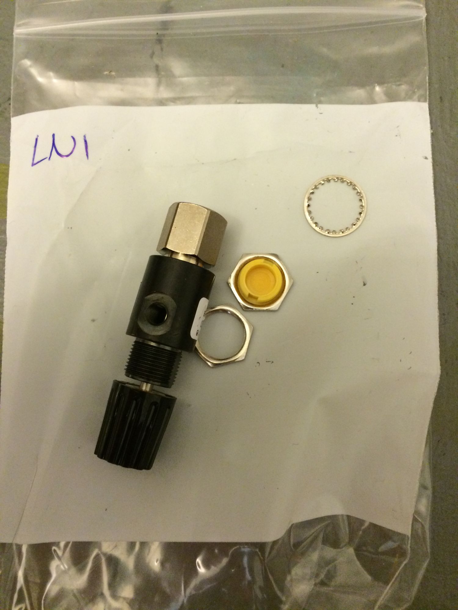
but I decide to use an Industrial High Quality Pneumatic Flow Control Needle Valves with inter changeable Barb Fitting and Swivel Port.
Here is the pictures of the Flow Control Needle Valves and the assortment of fittings that I bought to make sure fit my Samco hoses.


I also make a custom bracket so it can be solidly mounted near the valve cover and here it is mounted, (NOTE that the valve happened to come with a YELLOW top screw cap which perfectly match my Samco hose, I don't even notice this until I received it yesterday so Lucky me


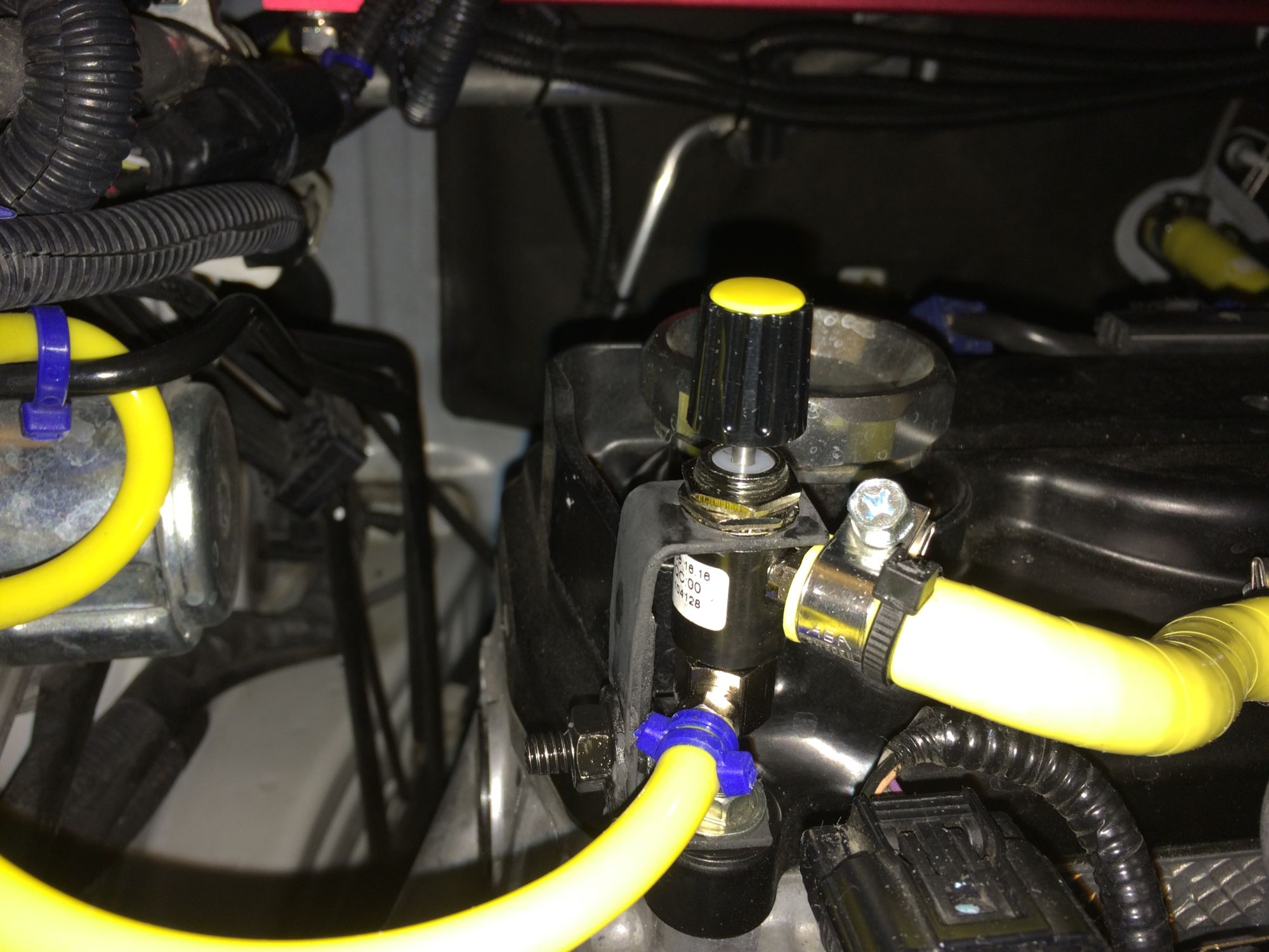

Then I start by calculating how many rotation before it is fully closed,
turn out it is 7 turn. (oh, I put a drop of paint on the knob (white paint) to mark the dial)...
I start with 3 turn close then test drive and see if there is still rattle.
After 4.5turn close, the rattle is almost gone except if I shift at redline
(it rattle right near redline),
so I close it more until it hit the sweet spot at 5.25 turn where it is now no longer rattle and I make sure the boost that goes into AEM MAP sensor is
still correct and respond fast.
There is the solutions
So happy that I can now drive my car without sound like a broken car and only Sweet Whine of Supercharger
Turn out it is not rattle, but it is a PULSATION of Air inside the Samco Vacuum Hose that connect the Sprintex Manifold to the AEM MAP on board boost sensor.
It only make a rattling noise when I am in gear and the car is under load.
If I rev it when stationary, it would not make any noise.
This rattling noise is common with others who install a Boost Gauge with vacuum line going into the gauge itself. (manual boost gauge).
There are several solutions,
a. Using a nipple that had a restrictor inside
b. Using small inline FUEL Filter
c. Using combination of both A. and B.
d. Using somekind of air valve to limit the flow of air (but NOT affect the pressure).
Many people use aquarium air valve to regulate this,
but I decide to use an Industrial High Quality Pneumatic Flow Control Needle Valves with inter changeable Barb Fitting and Swivel Port.
Here is the pictures of the Flow Control Needle Valves and the assortment of fittings that I bought to make sure fit my Samco hoses.


I also make a custom bracket so it can be solidly mounted near the valve cover and here it is mounted, (NOTE that the valve happened to come with a YELLOW top screw cap which perfectly match my Samco hose, I don't even notice this until I received it yesterday so Lucky me


Then I start by calculating how many rotation before it is fully closed,
turn out it is 7 turn. (oh, I put a drop of paint on the knob (white paint) to mark the dial)...
I start with 3 turn close then test drive and see if there is still rattle.
After 4.5turn close, the rattle is almost gone except if I shift at redline
(it rattle right near redline),
so I close it more until it hit the sweet spot at 5.25 turn where it is now no longer rattle and I make sure the boost that goes into AEM MAP sensor is
still correct and respond fast.
There is the solutions

So happy that I can now drive my car without sound like a broken car and only Sweet Whine of Supercharger

#19
Hello,
I got it from Merlin Motorsports in UK.
Their price with shipping is actually cheaper than buy it here in USA

Here is the link:
https://www.merlinmotorsport.co.uk/s...cone-hose-kits
#20
Hello,
I got it from Merlin Motorsports in UK.
Their price with shipping is actually cheaper than buy it here in USA
Here is the link:
https://www.merlinmotorsport.co.uk/s...cone-hose-kits
I got it from Merlin Motorsports in UK.
Their price with shipping is actually cheaper than buy it here in USA

Here is the link:
https://www.merlinmotorsport.co.uk/s...cone-hose-kits
Thread
Thread Starter
Forum
Replies
Last Post
Myxalplyx
3rd Gen GK Specific Fit Engine Modifications, Motor Swaps, ECU Tuning Sub-Forum
10
06-26-2015 10:59 PM
bensenvill
2nd Gen GE8 Specific Fit Engine Modifications, Motor Swaps, ECU Tuning Sub-Forum
26
12-23-2014 05:39 PM
Myxalplyx
Fit Engine Modifications, Motor Swaps, ECU Tuning
4
12-19-2014 11:15 AM
s0x
Fit Engine Modifications, Motor Swaps, ECU Tuning
5
10-13-2014 06:41 AM


